Download
1 / 14
140 likes | 214 Views

E N D
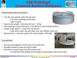
Electronics and Data Acquisition system for prototype INO-ICAL detectorA.Behere1, V.B.Chandratre1, S.D.Kalmani2, N.K.Mondal2, P.K.Mukhopadhyay1,B.K.Nagesh2, S.K.Rao2, L.V.Reddy2, M.N.Saraf2, B.Satyanarayana2,R.S.Shastrakar1, R.R.Shinde2, *S.S.Upadhya21Electronics Division, BARC, Mumbai ; 2DHEP, TIFR, Mumbai. * email: upadhya@tifr.res.inPresented by Prof Vivek Datar, NPD, BARC OBJECTIVES: • Feasibility study of INO prototype detector ( RPC ) of dimension 1m3 • Fast development of electronics to study the detector performance Outline of Talk: • Introduction • Experimental set up • Front end Analog Electronics • Trigger logic • Software • Present configuration of Electronics setup • Modules developed in-house • Performance and Conclusion DAE-SNP07 S.S.Upadhya
INO Prototype Detector CAMAC back end DETECTOR • Detector Specifications: • 14 layers of RPCs • RPC has X & Y-planes (orthogonal strips) • Each plane gives 32 pick up signals • Total no. of channels = 14x2x32 • = 896 RTC Final Trigger INO controller TDC Readout Mod. Monitor Scaler CAMAC Controller RPC 60mm iron Z=1m Front end Electronics Y=1m X=1m • Informations to be recorded on every valid trigger: • Event time up to micro secs (RTC) • Particle interaction tracks (X-Y pick-up signal boolean status of each layer) • relative time of interaction along the layers of RPCs (TDCs) • Design Considerations: • Flexibility and scalability • Fast implementation using available resources and expertise • Custom design standard at front end and CAMAC standard at back end. BACK DAE-SNP07 S.S.Upadhya
Electronics Set up Layer 1 (X&Y) Amplifier and Discriminator Processing and Monitoring SIGNAL ROUTERS Trigger & TDC Control - Data Monitoring Front End • Main Sections of the setup: • Front End Electronics • Trigger logic • Event recording • Monitoring Layer 14 (X&Y) Amplifier and Discriminator Processing and Monitoring Back End CAMAC Controller Mon Scalers Eve Scalers RTC TDC Read out Controller TRIGGER CAMAC system • Daisy chain : interface between Front end and Back end electronics across layers for control, data transfer and monitoring • Event daisy chain : 1 each for 14 layers of X & Y planes • Monitor daisy chain: 8 no.s ( 1 each for every 4 layers in X & Y planes ) • Note: MAX length of a daisy chain can be 16 modulesBACK DAE-SNP07 S.S.Upadhya
Front end Analog Electronics • 8 channel Amplifier : • RPCs in avalanche mode gives very small • pulses of few mV and hence signal is amplified • Specifications : • placed close to pick-up strips • a gain of 75 • 100 ohm output impedance • rise time of 2 ns • Front End Discriminator: • Converts the pickup signals over set • threshold to digital signals (Diff ECL) • Specifications: • 16 channels per module • common threshold variable from 2 to 500mV • houses Trigger-0 logic also BACK DAE-SNP07 S.S.Upadhya
Trigger Logic For X-plane • in Front End Discriminator (FED) module[ TRIGGER 0 LOGIC - T0 trigger] • Pickup signals crossing set threshold converted to DIGITAL (diff ECL) ; typical rate ~200Hz • Every 8th pickup signals in a plane are logically ORed to get T0 signals (S1 to S8) Sn rate is 4x200= 800Hz • in Front End Processing (FEP) module[ TRIGGER 1 LOGIC - T1 trigger] • M fold coincidence of S1 to S8 signals (equivalent to M fold coincidence of consecutive pickup signals in a plane) • Final Trigger Module ( CAMAC std. )[ TRIGGER 2 LOGIC - T2 trigger ] • M fold signals(1F,2F,3F,4F) from all the X-planes are the inputs (diff LVDS) • MxN fold trigger is generated ie N fold coincidence of M fold (T1) triggers from consecutive planes typical MxN folds implemented are 1x5, 2x4, 3x3, 4x2 For Y-plane • Similarly MxN fold for Y-plane is generated Final Trigger is logical OR of MxN fold trigger from X and Y-planes • Final Trigger invokes DAq system via LAM to record the event information. • Eg: M = 1F :: S1+S2+….+S8 • M = 2F :: S1.S2 + S2.S3 + S3.S4 + ….. + S7.S8 + S8.S1 • M = 3F :: S1.S2.S3 + S2.S3.S4 + S3.S4.S5 + ….. + S7.S8.S1 + S8.S1.S2 • M = 4F :: S1.S2.S3.S4 + S2.S3.S4.S5 + ….. + S7.S8.S1.S2 + S8.S1.S2.S3 BACK DAE-SNP07 S.S.Upadhya
DAq. Software • DAq. Program has been developed in C under Linux • Main program displays Event data, Monitor Data as well as responds for user Key hit services • EVENT RECORDING • On a final trigger, DAq program records • Event time up to microsecond • TDC readings • Boolean status of all pickup signals • Useful Trigger rates • MONITORING • On a periodic Monitoring trigger ( 1Hz) • Monitor time recorded up to microsecond • Rates of selected set of channels are recorded • Next set of channels are selected for monitoring DAE-SNP07 S.S.Upadhya
LAM Handler Main program Read LAM Register SW & HW initialization Enable LAM Handler N Event Flag Display Event and Monitor Data Y Program control On LAM . Initiate data transfer from front end to Read-out module . Record RTC time, TDC, Event Scaler . Record Read-out module data . Write data to file Any Key N Y Key Hit Services Monitor Flag N Execute Services Y . Record RTC time . Record Monitor scalers . Select next set of channels . Clear Monitor scalers Quit N Y STOP RETURN DAq. Software BACK DAE-SNP07 S.S.Upadhya
EveCom EveCom EveCom EveCom Mon Mon Mon Mon 16 Chnl DISC 16 Chnl DISC 16 Chnl DISC 16 Chnl DISC FTO FTO 32 Chnl FEP 32 Chnl FEP 32 Chnl FEP 32 Chnl FEP EveCom EveCom EveCom EveCom Mon Mon Mon Mon CAMAC bus 16 Chnl DISC 16 Chnl DISC 16 Chnl DISC 16 Chnl DISC 16 Chnl DISC 16 Chnl DISC 16 Chnl DISC 16 Chnl DISC EveCom EveCom EveCom EveCom Mon Mon Mon Mon 32 Chnl FEP 32 Chnl FEP 32 Chnl FEP 32 Chnl FEP 16 Chnl DISC 16 Chnl DISC 16 Chnl DISC 16 Chnl DISC EveCom EveCom EveCom EveCom Mon Mon Mon Mon INO Controller INO Readout Module Monitor Scaler Chain 1 X plane Y plane (** Connections CDR & TTR are similar to X plane) Chain 1 Layer 1 signals Layer 1 signals Control and Data Router (CDR) Layer 2 signals Layer 2 signals Layer 3 signals Layer 3 signals Layer 4 signals Layer 4 signals Trigger and TDC Router (TTR) • Chain 2 Layer 5 to 8 • Chain 2 Layer 5 to 8 • Chain 3 • Chain 3 Layer 9 to 12 Layer 9 to 12 CAMAC Controller Final Trigger Module TDC RTC CAMAC bus Present configuration of Electronics Setup and DAq. System DAE-SNP07 S.S.Upadhya
Electronics and DAq. System RPC Detector Back end Electronics Front End Electronics BACK DAE-SNP07 S.S.Upadhya
Modules Developed in-house • Processing and Monitoring module: • Latches Boolean status of 32 pick up signals on a final trigger • Transfers latched data over event daisy chain • Select the channels for monitoring • Generates M fold trigger –T1 per plane • Board has data-ID, event-ID, monitoring-ID • one per plane ie total of 28 modules • Final Trigger Module: • M folds of all X & Y planes are inputs • Generates MxN folds and final trigger • Final trigger invokes LAM • Inputs and outputs of trigger logic are individually mask-able. • Counting of all triggers by built-in scalers • Boolean status of M fold signals are latched on final trigger for later reading • design is FPGA based DAE-SNP07 S.S.Upadhya
Control and Data Router: • Routes the control signals from controller to processing modules in the daisy chain. • Routes latched event data serially and monitor signals from processing modules to back end via daisy chains • Trigger and TDC Router: • Routes M fold signals from all the processing modules to Final Trigger modules • Routes 1F signals from each processing module to TDC module as TDC stops DAE-SNP07 S.S.Upadhya
INO Controller: • In Event process, SW initiates the Controller to flush data serially from all processing modules over event daisy chains. • In Monitoring process, It selects the channels to be monitored. • Event and monitoring parameters like event data transfer speed, data size, monitoring period etc. are user programmable via CAMAC interface • Diagnostic features for DAq. is supported. • Read-out Module: • Receives Event data over 2 serial connections and 8 pick-up signals for monitoring from respective chains. • Serial Data converted into 16bit parallel data and stored temporarily in FIFOs buffer. • program reads FIFO data via CAMAC interface BACK DAE-SNP07 S.S.Upadhya
Performance and Conclusion • Most of the relevant modules are fabricated in-house and integrated into the system. • The Electronic set up in conjunction with the prototype detector has been performing satisfactorily. • Serial data transfer is tested upto a baud rate of 1 Mbps. DAE-SNP07 S.S.Upadhya
Electronics and Data Acquisition system for prototype INO-ICAL detectorS.S.Upadhya , TIFR( on behalf of INO collaboration ) OBJECTIVES: • Feasibility study of INO prototype detector ( RPC ) of dimension 1m3 • Fast development of electronics to study the detector performance Outline of Talk: • Introduction • Experimental set up • Front end Analog Electronics • Trigger logic • Software • Typical Electronics setup and DAq. System • Modules developed in-house • Performance and Conclusion OBJECTIVES: • Feasibility study of INO prototype detector ( RPC ) of dimension 1m3 • Fast development of electronics to study the detector performance Outline of Talk: • Introduction • Experimental set up • Front end Analog Electronics • Trigger logic • Software • Typical Electronics setup and DAq. System • Modules developed in-house • Performance and Conclusion DAE-SNP07 S.S.Upadhya