Download
1 / 1
10 likes | 100 Views
Velocity Tracking of Moving Objects Using Ultrasound Chady Gemayel, Phani Chavalis, Ed Richter, and Arye Nehorai Department of Electrical and Systems Engineering. Abstract. Simulation: Signal Generation. Real Velocity Calculation.

E N D
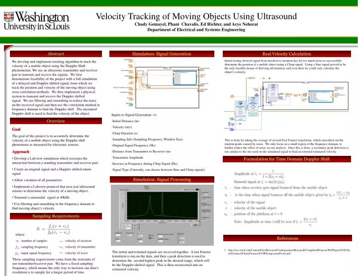
Velocity Tracking of Moving Objects Using UltrasoundChady Gemayel, Phani Chavalis, Ed Richter, and Arye Nehorai Department of Electrical and Systems Engineering Abstract Simulation: Signal Generation Real Velocity Calculation Initial testing showed signal from iteration to iteration has far too much noise to successfully determine the position of a mobile object using a Chirp signal. Using a Sine signal proved to be the only feasible means of deriving information, and even then we could only calculate the object’s velocity. This is done by taking the average of several Fast Fourier transforms, which smoothed out the random peaks caused by noise. We only focus on a small region of the frequency domain, to further reduce the effect of noise on our analysis. Once this is done, a secondary peak detection is run similar to the one used on the simulated signal to find an returned estimated velocity. We develop and implement tracking algorithm to track the velocity of a mobile object using the Doppler Shift phenomenon. We use an ultrasonic transmitter and receiver pair to transmit and receive the signals. We first demonstrate feasibility of the project with a full simulation of a delayed and Doppler shifted signal, from which we track the position and velocity of the moving object using cross correlation methods. We then implement a physical system to transmit and receive the Doppler shifted signal. We use filtering and smoothing to reduce the noise on the received signal and then use the correlation method in frequency domain to find the Doppler shift. The measured Doppler shift is used to find the velocity of the object. Inputs to Signal Generation .vi: -Initial Distance (m) -Velocity (m/s) -Chirp Duration (s) -Sampling Info (Sampling Frequency, Window Size) -Original Signal Frequency (Hz) -Distance from Transmitter to Receiver (m) -Transmitter Amplitude -Increase in Frequency during Chirp Signal (Hz) -Signal Type (Currently, can choose between Sine and Chirp signals) Overview • Goal • The goal of this project is to accurately determine the velocity of a mobile object using the Doppler shift phenomena as measured by ultrasonic sensors. • Approach • Develop a Labview simulation which recreates the interaction between a standing transmitter and receiver pair: • Create an original signal and a Doppler shifted return signal • Allow variation of all parameters • Implement a Labview protocol that uses real ultrasound sensors to determine the velocity of a moving object. • Transmit a sinusoidal signal at 40kHz • Use filtering and smoothing in the frequency domain to find moving object’s velocity Formulation for Time Domain Doppler Shift Simulation: Signal Processing Sampling Requirements • where: • : number of samples • : sampling frequency • : input signal frequency • : velocity of receiver • : velocity of transmitter • : velocity of wave References http://ese.wustl.edu/ContentFiles/Research/UndergraduateResearch/CompletedProjects/WebPages/fl10/ChadyGemayel/ChadyGemayelUGRSymposiumPoster.pdf The initial and returned signals are received together. A fast Fourier transform is run on the data, and then a peak detection is used to determine the second highest peak in the desired range, which will be the Doppler-shifted signal. This is then reconverted into an estimated velocity. These sampling requirements come from the restraints of our transmitter/receiver pair. We have a fixed sampling frequency, which means the only way to increase our data’s resolution is to sample for a longer period of time.