Download
1 / 26
260 likes | 354 Views
Budapest University of Technology and Economy Research Seminar October 2006. Standardisation and Interoperability of the Technology and equipment for BPL Systems. Key Points of Talk. Current Developments of BPL in the World Technical Restrictions and Limitations

E N D
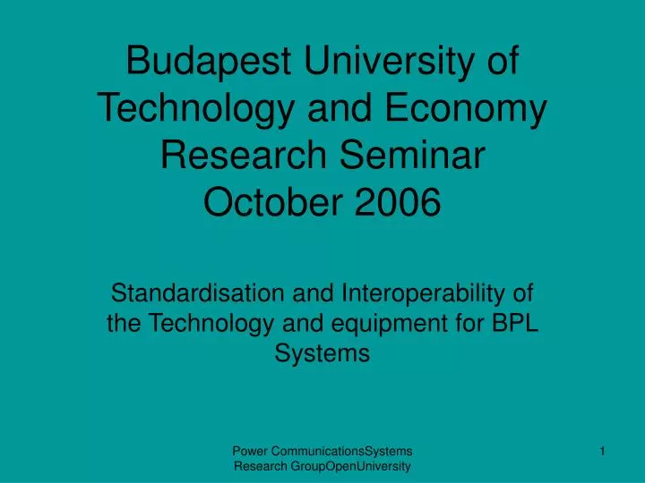
Budapest University of Technology and EconomyResearch SeminarOctober 2006 Standardisation and Interoperability of the Technology and equipment for BPL Systems Power CommunicationsSystems Research GroupOpenUniversity
Key Points of Talk • Current Developments of BPL in the World • Technical Restrictions and Limitations • Committee’s Responsible for Improving BPL systems • The way forward Power CommunicationsSystems Research GroupOpenUniversity
Key Committee Drivers For BPL • CISPR 22 ,I, Special committee for BPL Measurement; Established October 2005 • Three meetings so Far • European EMC Committee ;Code of Practice for Measurements • Cenelec SC205A BPL systems • ETSI BPL • IEEE BPL committee: EMC:Safety: Coupling • 6thFramework Programme “OPERA” Power CommunicationsSystems Research GroupOpenUniversity
Internet Backhaul network PLC Generic Model High Voltage Xmission Equipment pt to multi-pt CPE Phone(s) pt to pt Fibre Network PC Medium Voltage Grid (“Last Mile”) Low Voltage (“Last 100m”) In-Premise (“Last Inch”) * CPE - Customer Premise Equipment Power CommunicationsSystems Research GroupOpenUniversity
Overhead PLT Power CommunicationsSystems Research GroupOpenUniversity
PLC pilot projects in Europe LinaNET,Reykjavik/ascom Linanet/Siemens BKK,Bergen/Siemens Viken,Oslo/ascom Scottish & Southern Energy Elforsk,Stockholm/mainnet Vattenfall,Gotland/mainnet Nesa,Kopenhagen/ascom EviCom,Malmö/ascom EviCom,Malmö/Siemens EWEtel,Oldenburg/Siemens RWE,Essen/ascom EAM,Kassel/Siemens Avacon,Magdeburg/oneline CEGECOM,Luxembourg/ascom GEW,Köln/Siemens MVV,Mannheim/Mainnet FT-Cnet,France/ascom EnBW,Ellwangen/Siemens EdF,Strasbourg/ascom SSW,Salzburg/Siemens EVN,Wien/ascom DIAX,Fribourg/ascom Novacom/EnBW,Budapest/Siemens TIWAG,Fulpmes/ascom EdF/mainnet ESG,PPC, Linz/mainnet Union Fenosa/mainnet Enel,Bologna/ascom Endesa,Barcelona/ascom EdP,Lisbon/ascom Enel,Florence/mainnet Endesa,Sevilla/DS2 Power CommunicationsSystems Research GroupOpenUniversity
Worldwide PLC Activities Norwegen: Stadtwerke Bergen Schweden: Sydkraft, BirkaEnergi Finnland – EVU-Verband Island: LinaNet Reykjavik Energy China Provinz Sechuan UK/SSE Indianapolis, Boston D – RWE, EnBW, MVV, onelineA - TIWAG, EVN, Stw. Salzburg, EVO CH - DIAX Spanien Endessa Portugal EdP Italien Enel Korea Keyin Kuwait ITS Qatar Israel Mainnet, ITRAN, elLine Malaysia FibreCom Multimedia-Ministerium Brasilien: Copel Cemig InfoPaolo Südafrika (Siemens) Argentinien (ascom) Chile (Endesa) Power CommunicationsSystems Research GroupOpenUniversity
Frequency Spectrum Low Frequency Power Line Transmission USA: 50KHz to 450KHz(IEEE) Europe:3Khz to 148.5KHz(Cenelec50065) High Frequency Transmission 1MHz to 30MHz underground USA 1MHz to 80MHz for underground and overhead Power CommunicationsSystems Research GroupOpenUniversity
Deterministic Communication System –ADSL; VDSL;Cable Modems • Unique frequency specification • Characteristic impedance • Minimum noise • Constant bandwidth • Standard architecture • No common mode current and Potential Radiated emission to cause interference Power CommunicationsSystems Research GroupOpenUniversity
PLT System Communication Non-Deterministic • Unique frequency specification • Characteristic impedance • Minimum noise • Constant bandwidth • Standard architecture Power CommunicationsSystems Research GroupOpenUniversity
Leaky cables @1Mhz to 30Mhz • At these frequencies not all the signal is transmitted down the cable-it leaks power • So some of the high frequency signal emanates as electromagnetic radiation • Hence power cables can be considered as linear antennas and • Low efficiency Power CommunicationsSystems Research GroupOpenUniversity
In-House Communications • Limited to inside buildings of all types; • Industrial • Commercial • Residential • Different electrical structures: single and 3 phase :Ring Main & Tree &Branch • wide range of services • Frequency range 1 to 30Mhz to80MHz Power CommunicationsSystems Research GroupOpenUniversity
Key Parameters for Investigation • Investigation of Key parameters of Broadband Power Line Carrier communications • Impedance of the power Line over the frequency range 3KHz to 30MHz • Signal Injection Power: symmetrical and asymmetrical • Conducted current • Common mode current –Potential forRadiated emission from power line Power CommunicationsSystems Research GroupOpenUniversity
Key Parameters forInvestigation(2) • Longitudinal Conversion Loss (LCL) • Regression of signal • K Factor • Noise Floor measurements • Relationship between the Impedance of Line , LCL, with type of devices connected to the line. • Effects of network architecture on radiated emission • Mechanisms for understanding emissions in terms of these parameters Power CommunicationsSystems Research GroupOpenUniversity
Key Parameters for Investigations(3) • Noise floor measurements for PLT , Cable systems and XDSL systems • Inter-modulation products (IMP’s) • Ingress and egress noise • Variation of all these parameters with different frequency ranges Power CommunicationsSystems Research GroupOpenUniversity
Established Communication Services in the 1MHz to 30MHz • Broadcasting Channels • Amateur Radio • Mobile Communications • Distress frequencies • Military communications • Radio astronomy Power CommunicationsSystems Research GroupOpenUniversity
Sources of Interference • Noise caused by impedance mismatch • Impulse noise ingress from electrical appliances • Narrow band ingress from SW broadcast • Attenuation of the network • impedance variations • general interference • poor power quality Power CommunicationsSystems Research GroupOpenUniversity
Spectrum & Technologies 30 kHz 300 kHz 3 MHz 30 MHz MEDIUM FREQUENCY LOW FREQUENCY HIGH FREQUENCY GROUND WAVE SKY WAVE SPACE WAVE ADSL 25 kHz - 1.1 MHz VDSL 1.1 - 30 MHz DPL 1.1 - 30 MHz Power CommunicationsSystems Research GroupOpenUniversity
Scope IONOSPHERE SKY WAVE 3 - 30MHz Q SPACE WAVE 0.1 - 30MHz GROUND WAVE 0.1 - 3MHz LONDON ROME G NEAR FIELD SUBURBAN RURAL Average UK ground 0 km 5 km 200 km 1500 km Power CommunicationsSystems Research GroupOpenUniversity
Physical structure of LV network Armoured Cable • Underground & overhead distribution • Armoured cable • Conditioning units (CU) may be used Conditioning Unit (CU) Network MV network LV network Source: York EMC Services Ltd CU Internal mains network LV network SUBSTATION Data network CU Data port Power CommunicationsSystems Research GroupOpenUniversity
Coupling via the Mains Network LN 50Ω 50µH Source Victim Attenuation, dB/30m 30 20 10 Distribution network Mains only Power CommunicationsSystems Research GroupOpenUniversity 0.1 1 10 MHz Frequency
Radiated emission Mains cable Equip1 Mains cable plc1 Conducted emission through mains Conductio through earth impedance Radiated emission cable to cable Mains cable input Mains cable Radiated emission case to case plc2 External mains interference Electromagnetic radiated emission and coupling Interference Power CommunicationsSystems Research GroupOpenUniversity
Radiated Emission standards in the world Power CommunicationsSystems Research GroupOpenUniversity Fv,sbsbbbmb #bmb
An Electromagnetic ArchitectureFor “Manchester” City England What Type of Electromagnetic architecture? • 5 Engineering universities • International airport • Heavy Industry with machines and electrical systems • including British Aerospace : Car Manufactures • Many small electrical engineering companies • All these contribute to the continous noise floor Power CommunicationsSystems Research GroupOpenUniversity
Conclusions and Forward • More research into the EMC components of BPL • More measurements throughout the World • Investigation of cable types and age • Greater Understanding of Power Requirements of system • Keep In contact Power CommunicationsSystems Research GroupOpenUniversity