Download
1 / 74
750 likes | 852 Views
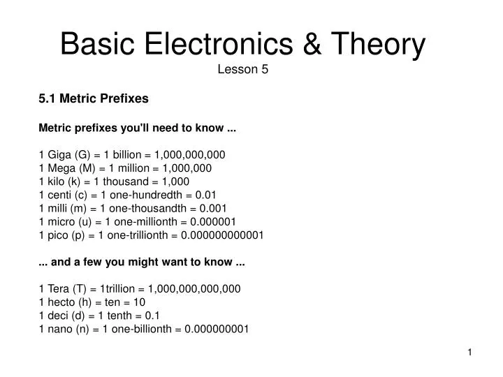
Basic Electronics & Theory Lesson 5. 5.1 Metric Prefixes Metric prefixes you'll need to know ... 1 Giga (G) = 1 billion = 1,000,000,000 1 Mega (M) = 1 million = 1,000,000 1 kilo (k) = 1 thousand = 1,000 1 centi (c) = 1 one-hundredth = 0.01 1 milli (m) = 1 one-thousandth = 0.001

E N D
Basic Electronics & TheoryLesson 5 5.1 Metric Prefixes Metric prefixes you'll need to know ... 1 Giga (G) = 1 billion = 1,000,000,000 1 Mega (M) = 1 million = 1,000,000 1 kilo (k) = 1 thousand = 1,000 1 centi (c) = 1 one-hundredth = 0.01 1 milli (m) = 1 one-thousandth = 0.001 1 micro (u) = 1 one-millionth = 0.000001 1 pico (p) = 1 one-trillionth = 0.000000000001 ... and a few you might want to know ... 1 Tera (T) = 1trillion = 1,000,000,000,000 1 hecto (h) = ten = 10 1 deci (d) = 1 tenth = 0.1 1 nano (n) = 1 one-billionth = 0.000000001
Basic Electronics & TheoryLesson 5 5.1 Metric Prefixes The prefix enables us to reduce the amount of zeros that are used in writing out large numbers. For example... instead of saying that the frequency of my signal is 1,000,000 Hz (Hertz or cycles per second) I can say that it is 1,000 kilohertz (kHz) or even 1 Megahertz (MHz). The prefix enables us to write the number in a shorter form. This especially becomes useful when we need to measure VERY large or VERY small numbers.
Basic Electronics & TheoryLesson 5 • 5.1 Metric Prefixes Mega- (one million; 1,000,000) • Just to make certain that this stuff makes sense, lets go back and look at large frequencies again. • 1,000 Hz = 1 kHz • "One thousand Hertz equals one kilohertz" • 1,000,000 Hz = 1 Mhz • "One million Hertz equal one megahertz" • So how many kilohertz are in one megahertz? 1000 kHz = 1 MHz • "One thousand kilohertz equals one megahertz" • So if your radio was tuned to 7125 kHz, how would you express that same frequency in megahertz? • 1000 kHz = 1 MHz || 7125 kHz = 7.125 MHz • (It takes 1000 kilohertz to equal 1 megahertz, so 7125 kilohertz would equal 7.125 megahertz.)
Basic Electronics & TheoryLesson 5 5.1 Metric Prefixes Mega- (one million; 1,000,000) Lets do another frequency problem. This time, your dial reads 3525 kHz. What is the same frequency when expressed in Hertz? This should be simple... 1 kHz = 1000 Hz || 3525 kHz = 3,525,000 Hz (Notice that since we have to add three zeros to go from 1 kHz to 1000 Hz, we must also do the same to go from 3525 kHz to 3,525,000 Hz.) Now, let's work another frequency problem, except we're going to do it backwards. Your displays shows a frequency of 3.525 MHz. What is that same frequency in kilohertz? 1 MHz = 1000 kHz || 3.525 MHz = 3525 kHz (See how the 1 became 1000? To go from megahertz to kilohertz, you multiply by 1000. Try multiplying 3.525 MHz by 1000 to get your frequency in kilohertz.)
Basic Electronics & TheoryLesson 5 5.1 Metric Prefixes Giga- (one billion; 1,000,000,000) Now we're going to deal with an even larger frequency. Remember, kilo equals one thousand, and mega equals one million. What equals one billion? There is a prefix for one billion - Giga. One billion Hertz is one gigahertz (GHz). What if you were transmitting on 1.265 GHz? What would your frequency be in megahertz? How many millions equals one billion? 1 billion is 1000 millions, so 1 gigahertz (GHz) is 1000 megahertz (MHz). 1 GHz = 1000 MHz || 1.265 GHz = 1265 MHz As you begin to see how these metric prefixes relate to each other, it will become easier to express these large and small numbers commonly used in radio and electronics.
Basic Electronics & TheoryLesson 5 5.1 Metric Prefixes Milli- (one one-thousandth; 0.001) If you were to take an ammeter (a meter that measures current) marked in amperes and measure a 3,000 milliampere current, what would your ammeter read? First, what does milli- mean? Milli might be familiar to those of you who were already familiar with the ever popular centimeter. The millimeter is the next smallest measurement. There are 100 centimeters in 1 meter... there are also 1000 millimeters in 1 meter. So milli must mean 1 one-thousandth. If your circuit has 3,000 milliamps (mA), how many amps (A) is that? 1,000 mA = 1 A || 3,000 mA = 3 A
Basic Electronics & TheoryLesson 5 5.1 Metric Prefixes Now lets say, on a different circuit, you were using a voltmeter marked in volts (V), and you were measuring a voltage of 3,500 millivolts (mV). How many volts would your meter read? 1,000 mV = 1 V || 3,500 mV = 3.5 V How about one of those new pocket sized, micro handheld radio you're itching to buy once you get your license? One manufacturer says that their radio puts out 500 milliwatts (mW) , while the other manufacturer's radio will put out 250 milliwatts (mW). How many watts (W) do these radios really put out? 1000 mW = 1 W || 500 mW = 0.5 W 1000 mW = 1 W || 250 mW = 0.25 W
Basic Electronics & TheoryLesson 5 5.1 Metric Prefixes Pico- (one one-trillionth; 0.000000000001) Capacitors are devices that usually have very small values. A one farad capacitor is seldom ever used in commercial electronics (however I understand that they are sometimes used when a lot of stored up energy is needed for an instant). Usually, your run of the mill capacitor will have a value of 1 thousandth of a farad to 1 trillionth of a farad. This is the other end of the scale compared with kilo, mega, and giga. Now we'll learn about micro and pico. If you had a capacitor which had a value of 500,000 microfarads, how many farads would that be? Since it takes one million microfarads to equal one farad... 1,000,000 uF = 1 F || 500,000 uF = 0.5 F
Basic Electronics & TheoryLesson 5 5.1 Metric Prefixes Pico- (one one-trillionth; 0.000000000001) What if we had a capacitor with a value of 1,000,000 picofarads? Pico is a very, very small number, so to have 1 million pico farads is saying that the value is just very small instead of very, very small. One picofarad is one trillionth of a farad. One picofarad is also one millionth of a microfarad. So it takes one million picofarads (pF) to equal one microfarad (uF)... 1,000,000 pF = 1 uF By the way, just so you get a grasp of just how small a picofarad really is, remember, it would take one trillion (i.e. one million-million) picofarads (pF) to equal one farad (F), or... 1,000,000,000,000 pF = 1 F
Water flowing through a hose is a good way to imagine electricity Water is like Electrons in a wire (flowing electrons are called Current) Pressureis the force pushing water through a hose – Voltage is the force pushing electrons through a wire Friction against the holes walls slows the flow of water – Resistance is an impediment that slows the flow of electrons . Basic Electronics & TheoryLesson 5 5.2 Concepts of Current, Voltage, Conductor, Insulator, Resistance Current
Basic Electronics & TheoryLesson 5 • There are 2 types of current • The form is determined by the directions the current flows through a conductor • Direct Current (DC) • Flows in only one direction from negative toward positive pole of source • Alternating Current (AC) • Flows back and forth because the poles of the source alternate between positive and negative
Basic Electronics & TheoryLesson 5 5.2 Concepts of Current, Voltage, Conductor, Insulator, Resistance Conductors and Insulators There are some materials that electricity flows through easily. These materials are called conductors. Most conductors are metals. Four good electrical conductors are gold, silver, aluminum and copper. Insulators are materials that do not let electricity flow through them. Four good insulators are glass, air, plastic, and porcelain.
Basic Electronics & TheoryLesson 5 5.3 Concepts of Energy & Power, Open & Short Circuits The Open Circuit The open circuit is a very basic circuit that we should all be very familiar with. It is the circuit in which no current flows because there is an open in the circuit that does not allow current to flow. A good example is a light switch. When the light is turned off, the switch creates an opening in the circuit, and current can no longer flow. You probably figured that since there are "open circuits" that there are probably also "closed circuits". Well, a closed circuit is when the switch is closed and current is allowed to flow through the circuit. A fuse is a device that is used to create an open circuit when too much current is flowing.
Basic Electronics & TheoryLesson 5 5.3 Concepts of Energy & Power, Open & Short Circuits The Short Circuit A short circuit can be caused by incoming power wires (wires that are normally insulated and kept separate) coming in contact with each other. Since a circuit usually has resistance, and the power wires that "short out" have very little resistance, the current will tend to flow through the path of least resistance... the short. Less resistance at the same amount of voltage will result in more current to flow. Therefore a short circuit will have too much current flowing through it. What's the best way to stop a short circuit from doing damage (because it is drawing too much power from the source)? By using a fuse. Fuses are designed to work up to a certain amount of current (e.g. 1 amp, 15 amps, ...). When that maximum current is exceeded, then the wire within the fuse burns up from the heat of the current flow. With the fuse burnt up, there is now an "open circuit" and no more current flows.
Basic Electronics & TheoryLesson 5 5.3 Concepts of Energy & Power, Open & Short Circuits Power Every circuit uses a certain amount of power. Power describes how fast electrical energy is used. A good example is the light bulbs used in each circuit of your home. When you turn on a light bulb, light (and heat) are produced. This is because of the current flowing through a resistor built into the bulb. The resistance turns the electrical power into primarily heat, and secondarily light (assuming an incandescent bulb). Each light bulb is rated at a certain power rating. This is how much power the bulb will use in a normal 110 Volt house circuit. Three of the most popular power values for inside light bulbs are 60, 75, and 100 Watts (Power is measured in Watts). Which of these light bulbs uses the most power? The 100 Watt bulb uses the most power.
Basic Electronics & Theory • 5.4 Ohm’s Law • E = electromotive force (a.k.a. Voltage) • I = intensity (French term for Current) • R = resistance • Voltage: E = I x R (Volts) • Current: I = E / R (Amps) • Resistance: R = E / I (Ohms)
Basic Electronics & TheoryLesson 5 5.4 Ohm’s Law Calculating Voltage and Current and Resistance Current? There is a very easy way to determine how much current will flow through a circuit when the voltage and resistance is known. This relationship is expressed in a simple equation (don't let the word scare you... this is going to be easy as "pie"... Let's start with the "pie"... This circle will help you to know how to figure out the answer to these electrical problems. The three letters stand for... E = electromotive force (a.k.a. Voltage) I = intensity (French term for Current) R = resistance
Basic Electronics & TheoryLesson 5 5.4 Ohm’s Law Calculating Voltage and Current and Resistance Current? Lets say you have 200Volts hooked up to a circuit with 100 Ohms of resistance. How much current would flow? Since our "unknown" value in this problem is the current, then we put our finger over the "I". What you see is "E over R". This means you take the Voltage and divide it by the Resistance. This is 200 Volts divided by 100 Ohms. The result is 2 Amps. E = electromotive force (a.k.a. Voltage) I = intensity (French term for Current) R = resistance
Basic Electronics & TheoryLesson 5 5.4 Ohm’s Law Calculating Voltage and Current and Resistance Voltage? What if we wanted to find out the voltage in a circuit when we know the current and resistance? Go back to the "pie" and cover up the E. You're now left with I times R. How much voltage would you need in a circuit with 50 ohms and 2 amps? E=IxR... E=2x50... E=100 Volts. E = electromotive force (a.k.a. Voltage) I = intensity (French term for Current) R = resistance
Basic Electronics & TheoryLesson 5 5.4 Ohm’s Law Calculating Voltage and Current and Resistance Resistance? Finally, if you had a circuit with 90 Volts and 3 amps, and you needed to find the resistance, you could cover up the R... the result is E over I (Volts divided by Current). R=E/I... R=90/3... R=30 Ohms. This circuit would have 30 Ohms of resistance if it was hooked up to 90 Volts and 3 amps flowed through the circuit. Ohm's Law This relationship between voltage, current, and resistance is known as Ohm's Law. This is in honour of the man who discovered this direct relationship (his last name was Ohm). The relationship described in Ohm's Law is used when working with almost any electronic circuit.
Basic Electronics & Theory Memorizing Ohm's law Memorizing Ohm's law may sound like a time consuming and daunting task, but if remember this little story you'll have it committed to memory for life within a few minutes! An old Indian was walking across the plains one day and he saw an eagle soaring high in the sky over a rabbit. Now, picture things from the Indian's stand point - he sees the Eagle flying over the Rabbit: Say to yourself Indian equals Eagle over Rabbit. Now just use the first letter of each word: I = E over R, which is this formula: Voltage: E = I x R (Volts) Current: I = E / R (Amps) Resistance: R = E / I (Ohms)
Basic Electronics & Theory Memorizing Ohm's law However, from the Rabbit's point of view, he sees things a little differently. The Rabbit looks out and sees the Eagle flying over the Indian. Say to yourself Rabbit equals Eagle over Indian. Now just use the first letter of each word: R = E over I, which is this formula: Voltage: E = I x R (Volts) Current: I = E / R (Amps) Resistance: R = E / I (Ohms)
Basic Electronics & Theory Memorizing Ohm's law Finally, the Eagle up in the sky sees both the Indian and the Rabbit standing on the ground together. Say to yourself Eagle equals Indian and Rabbit together. Now just use the first letter of each word: E = IxR, which is this formula: Now if you simply remember the story of the Indian, Eagle and Rabbit, you will have memorized all three formulae! Voltage: E = I x R (Volts) Current: I = E / R (Amps) Resistance: R = E / I (Ohms)
Basic Electronics & Theory Memorizing Ohm's law So now we have 3 different ways that we can algebraically express Ohm's Law. or or But of what significance is it? Here is the gist of it. If we know 2 out of the 3 factors of the equation, we can figure out the third. Let's say we know we have a 3 Volt battery. We also know we are going to put a 100 W resistor in circuit with it. How much current can we expect will flow through the circuit? Without Ohm's Law, we would be at a loss. But because we have Ohm's Law, we can calculate the unknown current, based upon the Voltage and Resistance. Voltage: E = I x R (Volts) Current: I = E / R (Amps) Resistance: R = E / I (Ohms)
Basic Electronics & TheoryLesson 5 Power calculations • The unit used to describe electrical power is the Watt. • The formula: Power (P) equals voltage (E) multiplied by current (I).P = I x E
Basic Electronics & TheoryLesson 5 • Power calculations (cont) • How much power is represented by a voltage of 13.8 volts DC and a current of 10 amperes. • P = I x E P = 10 x 13.8 = 138 watts • How much power is being used in a circuit when the voltage is 120 volts DC and the current is 2.5 amperes. • P = I x E P = 2.5 x 120 = 300 watts
Basic Electronics & TheoryLesson 5 • Power calculations (cont) • You can you determine how many watts are being drawn [consumed] by your transceiver when you are transmitting by measuring the DC voltage at the transceiver and multiplying by the current drawn when you transmit. • How many amperes is flowing in a circuit when the applied voltage is 120 volts DC and the load is 1200 watts. • I = P/E I = 1200/120 = 10 amperes.
Basic Electronics & Theory Memorizing Ohm's law Power Formula P= I x E Lets try some examples we are familiar with; P= 60 watt light bulb E=120 volts I= .5 amps P=100 watt light bulb E=120 volts I=.83 amps Electric Kettle consumes P=900 watts E=120 volts I= 7.5 amps Electric Toaster P= 1200 watts E=120 volts I=10 amps Power: P = I x E (Watts) Current: I = P / E (Amps) Voltage: E = P/ I (Volts) E = Electromotive Force aka Volts I = Intensity aka Current
Basic Electronics & TheoryLesson 5 5.5 Series & Parallel Resistors Series circuits A series circuit is a circuit in which resistors are arranged in a chain, so the current has only one path to take. The current is the same through each resistor. The total resistance of the circuit is found by simply adding up the resistance values of the individual resistors: equivalent resistance of resistors in series : R = R1 + R2 + R3 + ...
Basic Electronics & TheoryLesson 5 5.5 Series & Parallel Resistors Series circuits A series circuit is shown in the diagram above. The current flows through each resistor in turn. If the values of the three resistors are: With a 10 V battery, by V = I R the total current in the circuit is: I = V / R = 10 / 20 = 0.5 A. The current through each resistor would be 0.5 A.
Basic Electronics & TheoryLesson 5 5.5 Series & Parallel Resistors Series circuits R = R1 + R2 + R3 + ... R1=100 ohms R2=150 ohms R3=370 ohms RT= ? ohms
Basic Electronics & TheoryLesson 5 5.5 Series & Parallel Resistors Series circuits R = R1 + R2 + R3 + ... R1=100 ohms R2=150 ohms R3=370 ohms RT= 620 ohms
Basic Electronics & TheoryLesson 5 5.5 Series & Parallel Resistors Parallel circuits A parallel circuit is a circuit in which the resistors are arranged with their heads connected together, and their tails connected together. The current in a parallel circuit breaks up, with some flowing along each parallel branch and re-combining when the branches meet again. The voltage across each resistor in parallel is the same. The total resistance of a set of resistors in parallel is found by adding up the reciprocals of the resistance values, and then taking the reciprocal of the total: equivalent resistance of resistors in parallel: 1 / R = 1 / R1 + 1 / R2 + 1 / R3 +...
Basic Electronics & TheoryLesson 5 5.5 Series & Parallel Resistors Parallel circuits A parallel circuit is shown in the diagram above. In this case the current supplied by the battery splits up, and the amount going through each resistor depends on the resistance. If the values of the three resistors are: With a 10 V battery, by V = I R the total current in the circuit is: I = V / R = 10 / 2 = 5 A. The individual currents can also be found using I = V / R. The voltage across each resistor is 10 V, so: I1 = 10 / 8 = 1.25 A I2 = 10 / 8 = 1.25 A I3=10 / 4 = 2.5 A Note that the currents add together to 5A, the total current.
Basic Electronics & TheoryLesson 5 5.5 Series & Parallel Resistors Parallel circuits 1 / R = 1 / R1 + 1 / R2 + 1 / R3 +... R1=100 ohms R2=100 ohms R3=100 ohms RT= ? Ohms
Basic Electronics & TheoryLesson 5 5.5 Series & Parallel Resistors Parallel circuits 1 / R = 1 / R1 + 1 / R2 + 1 / R3 +... R1=100 ohms R2=100 ohms R3=100 ohms RT= ? Ohms 1/100 + 1/100 + 1/100 = .01 + 01 + .01 = .03 1/.03= 33.33 ohms
Basic Electronics & TheoryLesson 5 5.5 Series & Parallel Resistors A parallel resistor short-cut If the resistors in parallel are identical, it can be very easy to work out the equivalent resistance. In this case the equivalent resistance of N identical resistors is the resistance of one resistor divided by N, the number of resistors. So, two 40-ohm resistors in parallel are equivalent to one 20-ohm resistor; five 50-ohm resistors in parallel are equivalent to one 10-ohm resistor, etc. When calculating the equivalent resistance of a set of parallel resistors, people often forget to flip the 1/R upside down, putting 1/5 of an ohm instead of 5 ohms, for instance. Here's a way to check your answer. If you have two or more resistors in parallel, look for the one with the smallest resistance. The equivalent resistance will always be between the smallest resistance divided by the number of resistors, and the smallest resistance. Here's an example. You have three resistors in parallel, with values 6 ohms, 9 ohms, and 18 ohms. The smallest resistance is 6 ohms, so the equivalent resistance must be between 2 ohms and 6 ohms (2 = 6 /3, where 3 is the number of resistors). Doing the calculation gives 1/6 + 1/12 + 1/18 = 6/18. Flipping this upside down gives 18/6 = 3 ohms, which is certainly between 2 and 6.
Basic Electronics & TheoryLesson 5 5.5 Series & Parallel Resistors Circuits with series and parallel components Many circuits have a combination of series and parallel resistors. Generally, the total resistance in a circuit like this is found by reducing the different series and parallel combinations step-by step to end up with a single equivalent resistance for the circuit. This allows the current to be determined easily. The current flowing through each resistor can then be found by undoing the reduction process. General rules for doing the reduction process include: Two (or more) resistors with their heads directly connected together and their tails directly connected together are in parallel, and they can be reduced to one resistor using the equivalent resistance equation for resistors in parallel. Two resistors connected together so that the tail of one is connected to the head of the next, with no other path for the current to take along the line connecting them, are in series and can be reduced to one equivalent resistor. Finally, remember that for resistors in series, the current is the same for each resistor, and for resistors in parallel, the voltage is the same for each one
Basic Electronics & TheoryLesson 5 5.7 AC, Sinewave, Frequency, Frequency Units What is frequency? The number of cycles per unit of time is called the frequency. For convenience, frequency is most often measured in cycles per second (cps) or the interchangeable Hertz (Hz) (60 cps = 60 Hz), 1000 Hz is often referred to as 1 kHz (kilohertz) or simply '1k' in studio parlance. The range of human hearing in the young is approximately 20 Hz to 20 kHz—the higher number tends to decrease with age (as do many other things). It may be quite normal for a 60-year-old to hear a maximum of 16,000 Hz. We call signals in the range of 20 Hz to 20,000 Hz audio frequencies because the human ear can sense sounds in this range
The Relationship of Frequency and Wavelength The distance a radio wave travels in one cycle is called wavelength. V+ One Cycle 0V time V- One Wavelength
Basic Electronics & TheoryLesson 5 • Names of frequency ranges, types of waves • - Voice frequencies are Sound waves in the range between 300 and 3000 Hertz. • - Electromagnetic waves that oscillate more than 20,000 times per second as they travel through space are generally referred to as Radio waves.
Basic Electronics & TheoryLesson 5 • Relationship between frequency and wavelength • - Frequency describes number of times AC flows back and forth per second • - Wavelength is distance a radio wave travels during one complete cycle • - The wavelength gets shorter as the frequency increases. • - Wavelength in meters equals 300 divided by frequency in megahertz. • - A radio wave travels through space at the speed of light.
Basic Electronics & TheoryLesson 5 • Identification of bands • The property of a radio wave often used to identify the different bands amateur radio operators use is the physical length of the wave. • The frequency range of the 2-meter band in Canada is 144 to 148 MHz. • The frequency range of the 6-meter band in Canada is 50 to 54 MHz. • The frequency range of the 70-centimeter band in Canada is 420 to 450 MHz.
Basic Electronics & TheoryLesson 5 • 5.8 Decibels • The decibel is used rather than arithmetic ratios or percentages because when certain types of circuits, such as amplifiers and attenuators, are connected in series, expressions of power level in decibels may be arithmetically added and subtracted. • In radio electronics and telecommunications, the decibel is used to describe the ratio between two measurements of electrical power • Decibels are used to account for the gains and losses of a signal from a transmitter to a receiver through some medium (free space, wave guides, coax, fiber optics, etc.)
Basic Electronics & TheoryLesson 5 • 5.8 Decibels • A two-time increase in power results in a change of 3dB higher • You can decrease your transmitter’s • power by 3dB by dividing the original power by 2 • You can increase your transmitter’s • power by 6dB by multiplying the original power by 4
Basic Electronics & TheoryLesson 5 • 5.8 Decibels • If a signal-strength report is “10dB over S9” , if the transmitter power is reduced from 1500 watts to 150 watts, the report should now be S9 • If a signal-strength report is “20dB over S9”, if the transmitter power is reduced from 1500 watts to 150 watts the report should now be S9 plus 10dB The power output from a transmitter increases from 1 watt to 2 watts. This is a dB increase of 3.3 The power output from a transmitter increases form 5 watts to 50 watts by a linear amplifier. The power gain would be 10 dB.
Basic Electronics & TheoryLesson 5 • 5.9 Inductance
The Inductor • There are two fundamental principles of electromagnetics: • Moving electrons create a magnetic field. • Moving or changing magnetic fields cause electrons to move. • An inductor is a coil of wire through which electrons move, and energy is stored in the resulting magnetic field.
The Inductor • Like capacitors, inductors temporarily store energy. • Unlike capacitors: • Inductors store energy in a magnetic field, not an electric field. • The magnetic field is proportional to the current. When the current drops to zero the magnetic field also goes to zero.
The Inductor • Inductors are simply coils of wire. • Can be air wound (just air in the middle of the coil) • Can be wound around a permeable material (material that concentrates magnetic fields) • Can be wound around a circular form (toroid)