Download
1 / 17
170 likes | 276 Views
Plataforma de desenvolvimento. Foi escolhida a Plataforma de simulação MatLab/Simulink <---> FlighGear (X-Plane se encontra em processo de teste). Flight Gear Simulator. UDP 5500. Unidade Barometrica. Recomendação do filtro pasabaixa análógico 650Hz.

E N D
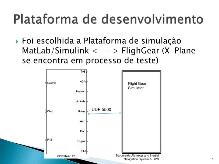
Plataforma de desenvolvimento • Foi escolhida a Plataforma de simulação MatLab/Simulink <---> FlighGear (X-Plane se encontra em processo de teste) Flight Gear Simulator UDP 5500 Barometric Altimeter and Inertial Navigation System & GPS
UnidadeBarometrica • Recomendação do filtropasabaixaanálógico 650Hz. • Recomendação de filtro Butterworth 2do ordenfc= 10Hz? • Programação do filtro digital interno do TI ADS1255. • O filtro digital interno TI trabalhaaté 32KSPS • A resposta do MPXA4115 = 1ms. • Filtro Inertial Navigation System & GPS
UnidadeBarometrica • No modelo foi considerada a função de transferencia do datasheet. Inertial Navigation System & GPS
AltimetroBarometrico • Testeda US Standard Atmosphere 1976 • Logo de verificaroslimitesdafunção no Wolfram Mathematicaparaacharoscoeficientesdaequação: • Unidades SI; • TROPOSPHERE 0 11 Km; • dTH=-0.0065; • R=287.052; • g= 9.80665; • T0=288.15; • P0=101325; • a=T0/-dTH • b=-dTH*R/g • 44330.8 • 0.190263 • h[p_]=a (1- (p/P0)b) • 44330.76923076923` (1-0.11158343153792875` p0.19026252593903117`) • 44330.8 (1-0.111583 p0.190263) • h[0] • h[101325] • 44330.8 • 0. Inertial Navigation System & GPS
RoC Rate of Climb • As dificuldades na derivação da altitude para achar a RoC fazerm necessário a escolha de um filtro. • Foi escolhido o filtro Wahsout Roc[s]=s/((1+T1s)(1+T2s)) fa <1/T1 e 1/T2 < N (largura de banda do ruido do sensor) Inertial Navigation System & GPS
IAS (Indicated Airspeed) Inertial Navigation System & GPS
GPS/INS complementary characteristics Inertial Navigation System & GPS
Descentralized GPS/INS integration 2000 Inertial navigation systems with geodetic applications Por Christopher Jekeli Inertial Navigation System & GPS
Difference between INS and GPS Descentralized processing Inertial Navigation System & GPS
Centralized GPS/INS integration 2000 Inertial navigation systems with geodetic applications Por Christopher Jekeli Inertial Navigation System & GPS
Cycle Ambiguaty Detection INS/GPS Centralized Integartion Inertial Navigation System & GPS
Dificuldades • Definir os passos de propagação e atualização.(asíncrono ou síncrono) Exemplo 85Hz propagação e 20Hz atualização. • O algoritmo de inversão de matrizes (erros por determinantes muito pequenos, precisão) Exemplo: Gauss Jordan • Desempenho esperado: Attitude , Latitude, Longitude e Altura. Inertial Navigation System & GPS
Dificuldades • Erros de integração fixed-step, fazemdivergerrapidamente o INS semKF. • Definiçãodaarquitetura do filtro (centralizado, desacoplado). • Definição do vetor de estados. • Definição do tipo de filtro: KF Linear, EKF, UKF, CKF. • No caso de usar um EKF, avaliar o metodoBierman-Thornton. Inertial Navigation System & GPS
Dificuldades 2008 Jay A. Farrell AIDEDNAVIGATION GPS with High Rate Sensors • Specification of the initial error covariance matrix P is often a cause of difficulties. Being careless in the definition of P, especially the portions of P related to the attitude errors, can have serious detrimental effects on the performance of the system. It is often best to use the sensor readings during a short period at the start of operation to initialize the state vector. Based on the statistics of the sensor measurements and the initialization period duration, the error covariance matrix P can be specified reasonably. Inertial Navigation System & GPS
Cascata Tress-Stage INS/GPS 2006 Eldredge Thesis IMPROVED STATE ESTIMATION FOR MINIATURE AIR VEHICLES Inertial Navigation System & GPS
Tree-Stage2004 DESIGN AND DEVELOPMENT OF DSP BASED GPS-INS INTEGRATED SYSTEMBhaktavatsala S Inertial Navigation System & GPS
Integration of INS and GPS System Using Kalman Filtering2004 Vikas Kumar Inertial Navigation System & GPS