Download
1 / 32
330 likes | 477 Views
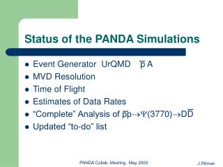
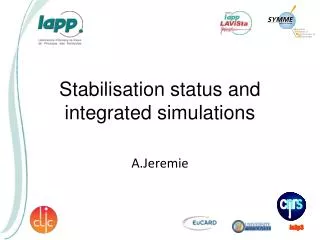
Status and details of coupler kick and wake simulations. V. Yakovlev, (in behalf of the team: N. Solyak, A. Latina, A. Lunin, and I. Gonin). 24 June, 2009. ILC RF cavity with the HOM and input couplers:. Downstream HOM coupler. Main coupler. RF cavity. Upstream HOM coupler.

E N D
Status and details of coupler kick and wake simulations V. Yakovlev, (in behalf of the team: N. Solyak, A. Latina, A. Lunin, and I. Gonin). 24 June, 2009
ILC RF cavity with the HOM and input couplers: Downstream HOM coupler Main coupler RF cavity Upstream HOM coupler
The couplers break the RF field symmetry and cause transverse RF kick. • The couplers break the symmetry of the cavity and cause transverse wake field. • Both RF kick and wake fields may be a reason of a beam emittance dilution. • DESY* made the first calculations of the RF kick and wake fields. The calculations show that both RF kick and wake fields may be a serious problem that could require the cavity improvement. • FNAL, SLAC, DESY, and TEMPF completed the calculations** • *I. Zagorodnov, and M. Dohlus, ILC Workshop, DESY,31 May, 2007. • **K.L.F. Bane, C. Adolphsen, Z. Li, M. Dohlus, I. Zagorodnov, I. Gonin, • A. Lunin, N. Solyak, V. Yakovlev, E. Gjonaj, T. Weiland, EPAC2008, • TUPP019.
RF kick RF voltage: U=(2PZ)1/2, Z–coax impedance; Simple estimations of the transverse fields caused by the main coupler: for P=300 kW and Z≈70 Ohms U ≈ 6 kV Transverse kick: Δpy∙c≈eEyΔZ ≈eU/D∙D/2=eU/2. The RF field calculation precision should be better than 10-5! Transverse kick caused by the couplers acts on a bunch the same direction for all the RF cavities of the linac. Real part may be compensated by the linac feedback system; Imaginary part dives the beam emittance dilution.
RF–kick calculation Three groups made rf kick simulations: 1. FNAL: N. Solyak, et al, EPAC2008, MOPP042 2. DESY: I. Zagorodnov, and M. Dohlus, LCWS/ILC 2007 3. SLAC: K.L.F. Bane, et al, EPAC2008, TUPP019 ALL the three groups have different results! *Probably, typo in [3]
Main reasons: • Effect is extremely small, about 5-6 orders of magnitude smaller than the longitudinal fields; • In additions, cancelation takes place between upstream and downstream coupler. It demands very high precision of the field simulations, better than 10-6, that is a severe challenge for all numerical methods and codes. • Possible other reasons: • Different calculated geometries or numerical models; • Different assumptions (loaded Q, etc); • Different numerical approximation of the fields (in some codes E and H fields are calculated with different precision that should be taken into account); • Different methodical convergence for the methods used.
Acceptable vertical emittance dilution in the ILC is to be smaller than 5 nm. • Emitannce dilution is proportional to the rf kick squared. • The most critical is vertical rf kick. • Calculated vertical kick differs ~6 times and, thus, the estimated vertical emittance dilution caused by rf kick ONLY may differ ~36 times! • FNAL and SLAC compared geometries. As a result, vertical rf kick Vy/Vz10-6calculated by SLAC,changed from -22.4+6.1i* to -4.6 +5.6i** • DESY (I. Zagorodnov) provided to FNAL the geometry used for simulations. Difference is found in the geometry description (no rounding, simplified coupler geometry, etc). Geometry was used for wake calculation. We have no information whether it was used for rf kick. DESY (red) and FNAL (blue) FNAL and SLAC (the same now, but the results still differ) *Z. Li, Wake Fest 2007; ** K.L.F. Bane, et al, EPAC2008
FNAL approach: 1. HFSS code that allows the non-uniform mesh; 2. A special three-zone mesh that allows accurate filed description near the axis. 3. Intermediate mesh necessary to match the fine mesh near the axis and regular mesh in the rest of the cavity; 4. A special symmetrized mesh pattern was used in order to reduce the mesh noise. Different ways of the mesh symmetrization near the axis were used; 5. The number of mesh nodes was up to 0.5106; 6. Cross-check of the direct rf kick calculations by Panofsky – Wenzel theorem application; 7. Investigation of the numerical noise influence. An attempt was done to apply Micro Wave Studio, but it demonstrate poor convergence and strong noise. However, it’s results do not contradict to the HFSS results. FNAL results are the most pessimistic!
Mesh generation for HFSS for high-precision field calculations near the axis: Regular mesh Fine mesh Intermediate mesh Total number of the mesh nodes is up to 500,000
Zoomed mesh near the axis: Regularmesh Intermediate mesh Fine mesh
Results of the main coupler simulations: (Strong coupling case)
Symmetrized mesh pattern with reduced noise: Intermediate mesh Intermediate mesh Fine mesh Fine mesh repeats the pattern of the intermediate one. Fine mesh
Electric field (Ex,Ey) snapshots Magnetic field (Hx,Hy) snapshots Axial transverse fields for HOM coupler at different RF phases: Noise in the cavity is caused by presence of the strong acceleration field. Note that H field is calculated in HFSS with lower precision than E field.
Kick dependence on the integration path UPSTREAM HOME DOWNSTREAM HOME+PC No dependence, that means that the cavity fields do not contribute to the kick.
CALCULATION OF RF KICK. UPSTREAM END Panofsky-Wenzel (PW) theorem (in order to cross-check direct calculations only) Direct integration of fields component (Lorentz force equation)
CALCULATION OF RF KICK. DOWNSTREAM END TOTAL RF KICK: The results of the three groups are to be cross-checked!
Transverse wakefield. • GdfidL simulations: • GdfidL was installed on FNAL 80-node cluster (courtesy to Warner Bruns). • Indirect method for the wake calculations; • Moving mesh and Strang splitting scheme; • Cubic mesh is used (hx=hy=hz); • For the scheme used in GdfidL one should use σz/hz≥4-6 in order to achieve convergence;
The GdfidL Electromagnetic Field simulator* -wakes: longitudinal and transverse * http://www.gdfidl.de
Horizontal (a) and vertical (b) kick per period after the different number of periods for σ = 0.2 mm (blue), 0.3 mm (red), and 0.6 mm (green). Note, that kx,ky<0 (GdfidL gives not k, but –k!).
a) b) Horizontal (a) and vertical (b) kick per period versus the mesh size for σ = 0.3 mm (blue), 0.6 mm (red), and 1.0 mm (green).
The wake field wake dependence on the longitudinal coordinate s for different mesh size for σ =0.3 mm. dWy/ds<0.
The horizontal (solid blue) and vertical (solid red) kick dependence versus the bunch length σ. Dashed curves show the kick dependences for the upstream coupler rotated by 180º versus the axis. *convergence was not checked. **no information about convergence
What is important for the emittance dilution: Simple model, = const along the linac. • where G is acceleration gradient, Vy/Vz is RF kick, k=2π/RF, RFis RF wavelength, is RF phase, Q is the drive bunch charge, Wy is vertical wake potential per unit length, s is the distance from the bunch center, s<<RF . Note that Wy/s does not depend on for small . • The first term is responsible for force that acts on the bunch particles the same way, and, thus, may be compensated using the beam alignment technique (if this term is small enough – A. Latina). • The second term is responsible for the kick different for the different parts of the bunch and, thus, cannot be compensated.
Mechanism of the emittance dilution caused by the RF kick: No acceleration Acceleration
● ● • For ML =-5. • No compensation*. • Emittance dilution is higher for longer bunch. • For BC it may be a problem. *Noted also by K. Bane. Emittance change vs. z calculated numerically (red) and analytically (blue).
Main Linac, average kick is compensated: where For the ILC cavity one has =(-7.3+11.1i)10-6, =-5.3, G=23.93 MeV/m (31.5 MeV/m in the structures)
In the Main Linac the coupler rf kick/wake does not look to be a big issue; • For bunch compressor it is an issue, because the bunches are much longer than in the ML: 6mm in the beginning and 0.3 mm after the compression. • Possible ways of compensation of the coupler rf kick and wake influence: • Crab cavity; • Girder rotation.
Two-stage BC: (A. Latina)
An idea of a compact detachable quarter wave coupler unit that provides axial symmetry of the RF field and the cavity geometry in the beam channel:
Azimuthally-symmetric coupler unit: Standard unit Non-detachable unit Detachable unit
Summary • The RF kick and coupler wake do not compensate each other. • The emittance dilution is proportional roughly to the bunch length squared. If it is not a problem for ML, it could be a problem for BC. • Possible means to cure the problem in BC may be • Crab cavity; • Girder rotation; • Axisymmetrical quarter-wave coupler units.