Download

1 / 19
1.25k likes | 2.51k Views
Instrument Landing System and Microwave Landing System. Instrument Landing System (ILS). A ground-based instrument approach system that provides precision guidance to an aircraft approaching and landing on a runway in IFR conditions.

E N D
Instrument Landing System (ILS) A ground-based instrument approach system that provides precision guidance to an aircraft approaching and landing on a runway in IFR conditions. It uses a combination of radio signals (for guidance) and high-intensity lighting arrays – approach lights, touchdown and centerline lights and runway lights (for visual information). It provides lateral (azimuth) guidance – using VHF, vertical (elevation) guidance – using UHF and also range guidance. Automatic pairing in receivers. Principle of lobe comparison. Three components – Localizer, Glide slope and Marker beacons.
Instrument Landing System – Localizer Primary component of ILS and provides azimuth guidance along extended centre line of runway. The localizer is a VHF radio transmitter and antenna (array) system using the same general range as VOR transmitters (between 108.10 MHz and 111.95 MHz) located typically 1,000 ft (300 metres) beyond the stopping end of the runway. The signal transmitted by the localizer consists of two vertical fan-shaped patterns that overlap, at the center. They are aligned with the extended centerline of the runway. The right side of this pattern, as seen by an approaching aircraft, is modulated at 150 Hz and is called the "blue" area. The left side of the pattern is modulated at 90 Hz and is called the "yellow" area. The overlap between the two areas provides the on-track signal.
Instrument Landing System – Localizer Receiver Located in the aircraft and combined with the VOR receiver in a single unit. The localizer signal activates the vertical needle called the track bar (TB). An aircraft approaching east of the extended centerline of the runway is in the area modulated at 150 Hz and the TB is deflected to the left. Conversely, if the aircraft is in the area west of the runway centerline, the 90 Hz signal causes the TB to deflect to the right. In the overlap area, both signals apply a force to the needle, causing a partial deflection in the direction of the strongest signal.
Instrument Landing System – Localizer Receiver At the point where the 90 Hz and 150 Hz signals are of equal intensity, the TB is centered, indicating that the aircraft is located precisely on the approach track.
Instrument Landing System – Glide slope The glide slope provides vertical guidance to the pilot during the approach. The ILS glide slope is produced by a ground-based UHF radio transmitter and antenna system, operating at a range of 329.30 MHz to 335.00 MHz providing 40 channels. The transmitter is located 750 to 1,250 feet (ft) down the runway from the threshold, offset 400 to 600 ft from the runway centerline.
Instrument Landing System – Marker Beacons 75 MHz fan-shaped beam transmission in the form of inverted cone to confirm exact range from the runway – visual and audio indications. Outer marker (7 km from the touch down point), Middle marker (1 km from the touch down point) and Inner marker (Not used in all airports).
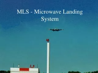
Microwave Landing System (MLS) The Microwave Landing System (MLS) is a new precision approach and landing navigation system and a replacement for Instrument Landing System. MLS – Here, an aircraft determines its location on-board from the signals that are emitted from the ground. In particular, the aircraft calculates its elevation, azimuth, and distance with respect to separate EL, AZ and DME transmitters on the ground. USA’s Time Reference Scanning Beam (TRSB) MLS (recommended by ICAO) and UK’s Doppler MLS (Not adopted by ICAO). MLS operates in the frequency band 5031.0 – 5190.7 MHz Features of MLS – availability of 200 channels, continuous angle and range information, improved signal quality, reduced requirement for siting and environment, availability of multiple flight paths, wider guidance coverage, missed approach guidance.
Microwave Landing System MLS functions (1) Approach azimuth Precise horizontal guidance. (2) Back azimuth Horizontal guidance for missed approach. (3) Approach elevation Precise vertical guidance. (4) Slant range Precision DME (DME/P) (5) Data communications Waypoint coordinates, weather conditions, runway conditions, equipment status.
Reference(s) N S Nagaraja, Elements of Electronic Navigation, Second Edition, Tata McGraw Hill, 1996. M M Poulose, P R Mahapatra and N Balakrishnan, “Microwave Landing System – A Favoured Alternative to Current ILS”, IETE Technical Review, Vol. 2, No. 11, 1985. James E Evans, Jack Capon and David A Shnidman, “Multipath Modeling for Simulating the Performance of the Microwave Landing System”, The Lincoln Laboratory Journal, Vol. 2, No. 3, 1989.