Download
1 / 26
260 likes | 415 Views
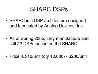
The Role of Programmable DSPs in 3G Handsets Chaitali Sengupta February, 2002. Overview. 3G Wireless Standards Functional view of 3GPP FDD-DS (WCDMA) Complexity analysis Mapping to architecture System design methodology. Wireless Cellular Systems. IS-95, GSM, IS-136

E N D
The Role of Programmable DSPs in 3G HandsetsChaitali SenguptaFebruary, 2002
Overview • 3G Wireless Standards • Functional view of 3GPP FDD-DS (WCDMA) • Complexity analysis • Mapping to architecture • System design methodology
Wireless Cellular Systems IS-95, GSM, IS-136 3rd Gen. (W-CDMA, …..) Backbone Network PSTN ISDN
Today’s Market % 2G - Today 2.5G - 2001 3G - 2003+ 9% PDC J-WCDMA GSM 66% W-CDMA GPRS IS136 EDGE 10% CDMA2000 IS95 15% IS95B 3G Wireless Standards Focus: 3GPP FDD Direct Sequence Mode (WCDMA)
Parameters defining the FDD-DS (WCDMA) 3G standard Parameter Description/value Carrier spacing 5 MHz Physical frame length 10ms Spreading factor 2k, k=2-8: UL, 2k, k=2-9: DL Channel coding Convolutional and Turbo Multirate Variable spreading / multicode Diversity techniques Multiple Tx antennas, Multipath Maximum data rates 384Kbps / 2Mbps 3GPP FDD-DS mode
Handset top level MMI PROTOCOL STACK ARM APPLICATION TASKS L1 SW DATA I/O L1 DBB HARDWARE DSP LCD, Camera, Etc. ABB RF
WCDMA System Downlink CHANNEL CODING, INTERLEAVER, ETC user’s bits SOURCE CODING ABB and RF SPREADING (BASE STATION) channel TRANSMITTER MRC (multipath and Tx diversity) ABB and RF DEINTERLEAVER DESPREADER RATE MATCHING DPE AND FINGER ALLOCATION CHANNEL ESTIMATION VITERBI/TURBO (CHANNEL DECODER) TIME TRACKING FREQUENCY TRACKING CRC CHECK (MOBILE USER) VOCODER, APPLICATION, ETC AUTOMATIC GAIN CONTROL RECEIVER
DBB Functional View DPE Finger alloc. DLL Viterbi I/Q data from A/D Despread MRC CCTrCH Turbo MAC (L2) de-ciphering Ch. Est. AFC to ABB & RF vocoder AGC Protocol stack (data) applications power control Measurements (neighbor & active set) Search 1 Layer3 (RRC) and Protocol stack (control) Directed search Set Maintenance RX Initial search applications ciphering vocoder to D/A Spreading (Chip-level) CCTrCH processing TX MAC (L2)
DBB Design Goals • Power, power, power • But: DBB is 10-25 % of total handset power • Flexibility • Evolving standards • Fine tuning in field • Scalability • Increasing data rates • Fast design cycle • Cost
Complexity Analysis Decoders Search/track Despread MRC A B C A: 8 Kbps voice only B: 12.2 Kbps voice + 384 Kbps data C: 2 Mbps data
HW/SW partitioning • Processing requirements depend on: • data rate, number of strong cells in the vicinity, wireless channel conditions, etc. • Primary tradeoff: power vs. flexibility • Dedicated HW: • Lowest power achievable for target functions • Lower flexibility to change • SW processing on low power DSPs • Higher flexibility
HW/SW partitioning • Category 1: Definitely in HW in the near term, • Very high MIPS or data I/O requirements • E.g. despreading • Category 2: Definitely in SW • Reasonable processing requirements • Requires flexibility • E.g. channel estimation • Category 3: In HW or SW based • Total power targets • Service scenarios for a specific implementation • Maximal Ratio Combining (MRC)
RX DPE Finger alloc. SW SW/HW HW DLL Viterbi I/Q data from A/D Despread MRC CCTrCH Turbo MAC (L2) de-ciphering Ch. Est. AFC to ABB & RF vocoder AGC Protocol stack (data) applications power control Measurements (neighbor & AS) Search 1 Layer3 (RRC) and Protocol stack (control) Directed search Set Maintenance Initial search applications ciphering vocoder to D/A Spreading (Chip-level) CCTrCH processing TX MAC (L2)
Co-processor approach • How to get flexibility at low power and cost? • “loosely coupled” (LCC) and “tightly coupled” (TCC) coprocessors • Based on average time to complete an “instruction” • Find a DSP/coprocessor partition that balances flexibility with a reasonable MIPs level on the DSP. • E.g., for Viterbi decoding: • the DSP could perform all the data processing up to the branch metric generation and • a coprocessor could perform the remaining high MIPS tasks of state metric update and trace back.
Tightly coupled coprocessors • TCC: task completes in the order of a few instruction cycles • Small amount of data processed per task • The DSP will freeze during the operation of the TCC. • TCC to main processor communication typically occurs through register reads and writes. • E.g. bit manipulation coprocessor • Processors that allow instruction set enhancement through hardware TCC units by means of a “Co-processor Port” • ARM processor (the ARM7TDMI), and the TMS320C55x processor • With time, the function of the TCC may migrate into the DSP
Tightly coupled coprocessors Memory System T Instruction C C decode I/f TCC Register file TCC instructions TMS320C55x
Loosely coupled coprocessors • LCC: Task will run in parallel to the DSP for many instruction cycles before it requires more interaction with the DSP. • Solves the serious problem of bus bandwidth • Computational units local to the data and arranged specifically for the data access required for a class of computations. • In time the LCC functionality will migrate to the DSP: • When DSP bus bandwidth and computational power is sufficient. • E.g. LCC for WCDMA chip rate processing (despreading, time tracking, path search) • Coprocessor can perform simple but high MIPS tasks • DSP provides configuration (e.g. averaging length for path search) • In effect the system is fully programmable within the domain of WCDMA chip rate processing.
Loosely coupled coprocessors Address Generation chips from AFE Input buffer PN Generation Datapath Analog Front end (AFE) Controller & Counters Instruction buffer DSP/ coprocessor interface Address Generation Output buffer SRAM DSP CORRELATOR COPROCESSOR
Centralized v.s. Distributed Architectures • The WCDMA system is parallel in nature • Centralized approach: • Resource sharing between functions • Centralized and more complex control • Lesser area • Distributed approach • Possibly lesser power as components may be switched off when idle • Less complex control • Most practical systems need a mix of both
Handset top level MMI PROTOCOL STACK ARM APPLICATION TASKS L1 SW DATA I/O L1 DBB HARDWARE DSP LCD, Camera, Etc. ABB RF
Control plane and Data processing • Use of a DSP and micro-controller combination • DSP is responsible for the heavy-duty signal processing • Control plane is divided between the DSP and the micro-controller. • DSP typically deals with low latency hard real time functions • Micro-controller provides • Centralized control of all physical layer resources • Higher layers in the protocol stack with decreasing real time content • Texas Instruments OMAPTM architecture consisting of an ARM9 and a C55x processor.
Modem and Applications • Same platform or multiple? • Issues: • Development logistics • Protecting the real time nature of the modem • Type approval • Power and cost of course! • In practice there will possibly be both types • Separate platforms: high end phones, • Single platform: low end primarily voice and less demanding applications
System Analysis Methodology • How to manage design of such complex systems with so many optimization criteria? • Top down methodology • Characterization of application • Control plane • Data plane • Characterization of architecture options • Abstract models of performance for fast simulations of application to architecture mapping.
Summary • 3G handset DBB has processing requirements several times higher than 2G • Power is the driving criteria followed by cost and flexibility • Completely DSP SW processing is not possible • Challenges: • Choice of system partitioning • Design of dedicated HW with sufficient flexibility working with programmable DSPs • Methodology to support such decisions!
Reference • The Role of Programmable DSPs in Dual Mode (2G+3G) Handsets. C. Sengupta, N. Veau, S. Sriram, Z. Gu, P. Folacci, S. Kinjo. Book chapter in: The Application of Programmable DSPs in Mobile Communications. Editors: A. Gatherer and E. Auslander
APPLICATION ARCHITECTURE Scenario (N) MAPPING Scenario (1) Components (e.g DSP core, peripherals, DMA) Platform Schedulers / rules (e.g. bus arbitration policies, DMA protocols, scheduling policies) Control plane Mapping options Resource consumption (of process mapped to component; in MHz, memory, IO) Processes Control flow (messages) Data flow System steady state Data plane SIMULATION (in VCC: data plane driven by control plane, no actual data processing or data transfer) PERFORMANCE (Total MHz, memory, I/O) Performance Simulation