Download
1 / 14
600 likes | 1.61k Views
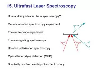
Introduction to DLTS (Deep Level Transient Spectroscopy) II. Advanced Techniques O. Breitenstein MPI MSP Halle. Outline: 1. Basic principles Application field of DLTS Principles of DLTS Basic measurement techniques 2. Advanced techniques Advanced DLTS measurement techniques

E N D
Introduction to DLTS (Deep Level Transient Spectroscopy) II. Advanced Techniques O. Breitenstein MPI MSP Halle
Outline: • 1. Basic principles • Application field of DLTS • Principles of DLTS • Basic measurement techniques • 2. Advanced techniques • Advanced DLTS measurement techniques • 3. (next time) Our DLTS system • - Philosophy • - Hardware • - User surface
Recapitulation: DLTS routine (repeating!) : reverse reduced or forward reverse Vr bias t 0 e- e- e- band diagram e- e- RF- capacitance t DC 0 t
DCmeas t t1 t2 t t2 t1 t t2 t1 DLTS signal = C(t1)-C(t2) Tpeak T DCpeak Generation of the DLTS signal opt. T low T high T "rate window": If T is slowly varying, at a certain temperature a DLTS peak occures
ln(en) DLTS e01 e03 e02 e02 e03 e01 T T3 T2 T2 T1 T1 T3 1000/T DLTS measurements at different rate windows allow one to measure Et This "Arrhenius plot" allows an identification of a deep level defect
h+ e- e- e- e- e- e- h+ e- e- e- e- xh h+ h+ h+ 2. Advanced DLTS measurement techniques 2.1. Possible samples: Schottky diodes or pn-junctions Schottky diode pn-junction reverse bias V = 0 xe forward bias minority carrier injection majority carrier flow
Schottky diodes: • Standard, easy to prepare, high quality demand ! • Only majority carrier traps visible, even under forward bias • pn-junctions: • reverse bias reduction up to 0V: "majority carrier pulse" • forward bias (injection): "minority carrier pulse" (MC) • MC pulse may reveal both minority and majority carrier traps • However, if opposite carrier capture dominates, traps may remain uncharged (invisible in DLTS) => basic limitation ! • Asymmetric doping concentration: signal from lower doped side • Other sample types: • Grain boundary (anti-serial Schottky diodes) =>bonded wafers • MIS devices • FETs ("conductivity DLTS") • point contacts at nanowires ? ...
e- h+ h+ e- e- h+ h+ h+ • 2.2. Optically excited DLTS (minority carrier DLTS, MCDLTS) • trap filling by optically excited minority carriers (hn > Eg) • reverse bias remains constant thermal equilibrium traps emptied (from holes) measurement hole emission filling pulse hole capture • allows investigation of minority carrier traps in Schottky diodes
Tpeakillumin. T Tpeakdark T • 2.3. Optical DLTS (ODLTS) • trap filling by bias pulses • continuous irradiation of IR light (< Eg) • optical emission additional to thermal emission • strong dependence on intensity and l illuminated dark • ODLTS allows to measure optical capture cross sections sopt(l) • connection between deep levels electrically detected (DLTS) and optically detected (absorption)
Tpeak T e- Tpeak e- T Tpeak e- T Tpeak e- T 2.4. Concentration depth profiling (pulse height scan) Vr t Vr t Vr t Vr t • linear dependence on Vp: homogeneous concentration !
Tpeak1 T Tpeak2 T Tpeak3 T Tpeak4 T 2.5. Measurement of field dependence of en;p (pulse height scan) Vr t Vr • quantitative evaluation: difference spectra (DDLTS) • field depencence indicates charged occupied state t Vr t Vr t
Tpeak T Tpeak T Tpeak T Tpeak T 2.6. Measurement of capture cross sections (pulse width scan) Vr t Vr t Vr • "real" capture cross section • measurement at different rate windows: T-dependence of CCS • injection: measurement of minority carrier CCS t Vr t
e - e - e - e - 2.7. Point defects and extended defects • all previous considerations referred to isolated point defects • "extended defects": dislocations, grain boundaries, precipitates ... • continuum of states, "broadened states" • emission probability depends on average occupation state • barrier-controlled capture, depending on occupation state point defect extended defect DLTS low occupation T DLTS high occupation tc log(timp) • extended defects show logarithmic capture behaviour
Summary • DLTS on Schottky diodes only reveals majority carrier taps • DLTS on pn junctions also reveals minority carrier traps • Optically excited DLRS (MCDLTS) also reveals minority carrier traps in Schottky diodes • ODLTS reveals optical trap parameters sopt(l) • There are special DLTS procedures for measuring: • - concentration depth profiles • - electric field dependence of en;p • - capture cross sections for electrons and holes • Extended defects are usually characterized by a logarithmic capture behaviour and often show non-exponential emission (broadened peaks) • Next time: Introduction of our own DLTS system