Download
1 / 12
130 likes | 224 Views
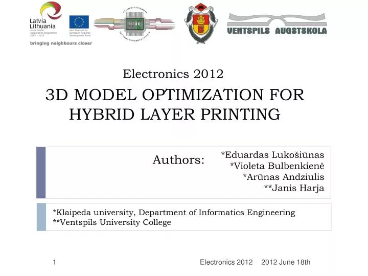
Electronics 201 2. * Eduardas Lukošiūnas * Violeta Bulbenkienė * Arūnas Andziulis **Janis Harja. 3d model optimization for hybrid layer printing. * Klaipeda university , Department of Informatics Engineering ** Ventspils University College. Authors:. Introduction.

E N D
Electronics 2012 *Eduardas Lukošiūnas *Violeta Bulbenkienė *Arūnas Andziulis **Janis Harja 3d model optimization for hybrid layer printing *Klaipeda university, Department of Informatics Engineering **Ventspils University College Authors: Electronics 2012
Introduction • In todays modern manufacturing the use of virtual models in prototype development has been increased. There is much software being used for creating 3D objects, such as: AutoCAD, 3ds Max, SolidWorks and others. • Hybrid Layered Manufacturing (HLM) is a Rapid Manufacturing (RM) process that builds metallic object prototypes from 3D virtual objects, through a combination of additive and subtractive processes. Electronics 2012
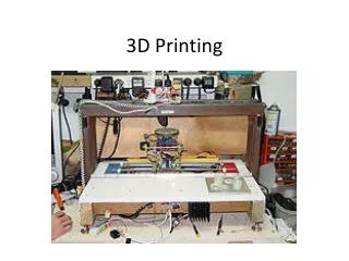
Hybrid Layered Manufacturing • Hybrid manufacturing consists of rapid printing that uses Gas Metal Arc Welding (GMAW) technology for layered deposition and computer numerical control (CNC) technology. Electronics 2012
Disadvandages • One of the main disadvantages is creating an accurately flat layer surface, to make it suitable for other layers. • Nowadays HML cannot create a flat surface. This problem is solved by milling a surface to make it flat. This kind of process takes a lot of time and needs to be improved. Electronics 2012
3D modeling of a printable object • The shape of a 3D model is rough and inaccurate, because it is divided in thick layers. The rough surface would later be trimmed by using CNC method. Electronics 2012
Bead shape calculation • During the printing a bead is created with a parabolic shape, therefor it‘s difficult to make a flat surface from these kind of beads. (1) (2) (3) (4) (5) Electronics 2012
Calculation of a distance between beads (1) (6) (7) (8) In order to get a flat surface we need to calculate a distance between bead trajectories. The distance needs to be small enough to make beads collide with each other to create a small amount of extra material for filling the gap between beads Electronics 2012
Calculation of a distance between beads (2) Modern three-dimensional printing equipment requires additional software packages, apart from those used in modeling. Such programs have their own structure, and some even in their own language. CNC milling equipment has its own language, whose structure is similar to the simulation code for SolidWorks software. While it is used for CNC calculations, it can as well be used for using those calculations to print beads by applying some changes in the code. (9) (10) (11) (12) (13) (14) Electronics 2012
Trajectory estimation Calculated bead trajectories. Part of the program code which is used for printing layers Electronics 2012
3D layer surface in 3ds max • Experimental studies were conducted in a virtual environment. For this reason 3ds Max software was used. According to the process parameters - bead printing speed, - wire cross-section radius and – wire pushing speed, visualisation of the collided beads was calculated. Electronics 2012
. Conclusions • After analysis and calculation to get a flat surface layer an algorithm was written. A 3D prototype model was created, which was used for experimental testing. Experiments have shown that it is possible to get a close to flat surface layers by using these process parameters: By using them we could calculate a distance between trajectories • This distance is the most optimal in order to obtain a smooth surface. • Due to gravity, surface tension force and electromagnetic force, the surface is not completely smooth, but close to being flat. To obtain a completely smooth surface, the CNC milling can be used to remove a small portion of the layer. Electronics 2012
Thank you for listening Electronics 2012