Download
1 / 31
310 likes | 473 Views
Parallel JPEG2000 Compression System. Performed by: Dmitry Sezganov, Vitaly Spector Instructor: Stas Lapchev, Artyom Borzin. Abstract. High data rate due to rapid growth in imaging capacity. Typical image data rates are several Gbits per second. Solution – image compression.

E N D
Parallel JPEG2000 Compression System Performed by: Dmitry Sezganov, Vitaly Spector Instructor: Stas Lapchev, Artyom Borzin
Abstract • High data rate due to rapid growth in imaging capacity. • Typical image data rates are several Gbits per second. • Solution – image compression. • Compression must be done prior to storage. • High compression ratio and performance is required. • Suitable compression algorithm should be used.
Abstract JPEG2000 Encoder JPEG2000 Decoder
Figure 2. Decoded test image IRLS20: PSNR vs. BitRate for JPEG, JPEG2000 and MPEG4 VTC codec. Figure 3. JPEG2000 VM2.0 decoded test-image: PSNR vs. BitRate for entire image, background and ROI. JPEG vs. MPEG vs. JPEG2000 We choose JPEG2000 algorithm.
Comparison Compression Rate: 130:1 Wavelet (7KB, 5922 bytes) JPEG2000 JPEG(7KB, 6220 bytes)
ADV202 Overview • Features of ADV202: • Single-Chip JPEG2000 Compression/Decompression cheap Solution. • Programmable Tile/Image Size. • Flexible pixel interface supporting 8, 10, 12, 14, 16-bit Y, Cr, Cb pixels. • Supports various interfaces (also DMA).
1m Satellite imagery 2.5km=5000pix Pixel=1/4 m² 8.5km/s 1m 2.5km
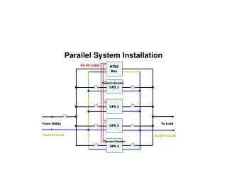
Requirements & Environment • Project requirements: • Building multi-unit compression prototype system. • Easy extension. • Input bit rate is 1.2Gbps. • Fast HW implementation. Environment: • Virtex-II Pro Development Board • ADV202 JPEG2000 Video Codec • PC
5000 Tile#0 Tile#1 4096 2500 Tile#2 Tile#3 Image tiling Input: • Data arrives line by line. • Input bit-rate 1.2Gbps 2 ADV202 devices. • 5000 pixels width 2500 to each ADV202. Output: • Synchronization needed. • Coded stream is taken by pieces from each ADV202, strongly in order.
Architecture Testing Unit Compression Unit 1.2 Gbps Generator Channel #1 Channel #2 Coded stream Coded stream and controls Raw stream • Testing Unit – simulates high bit rate camera. • Channel#1 – Ethernet; Channel#2 – Rocket IO; • Initialize the Generator with a picture. • The Generator sends the picture periodically.
Testing Unit PC Loading image through Ethernet Architecture Memory Logic Generator Duplicating and sending image through Rocket I/O channel Compression Unit Logic Tiled image data Codec PCB Bus Data flow
Commands GUI interfaces our system through the following command: • Reset. • Read/Write ADV202 register. • Read/Write Codec Controller register. • Start TX. • Stop TX. • Resume TX. • Statistic commands.
Network Topology • Each command – packet. • Packet ID defines packet’s source and destination. PowerPC2 PowerPC1 Controller • Load image (data for compression). • Command to PPC1 (from PC to PPC1). • Command to PPC2 (from PC to PPC2). • PPC1 to Controller (duplicated image stream). • Controller to PC (coded data). • PPC2 to PC (debug, statistics info).
Software • PPC runs web server • Has IP address, standard capabilities like answering pings. • Can be reached from any computer on the local network. • Windows socket programming for Ethernet. • MFC – writing GUI. • When PPC accepts connection from PC – full duplex conversation.
16 Rocket I/O Transceiver DCR Bus ISBRAM PPC405 Processor Block Packet Processing Engine I/F Logic TX 64 16 PLB BRAM 16 RX SDRAM Controller PLB BRAM Controller PLB Arbiter PLB PLB2OPB Bridge Ethernet Controller OPB Arbiter OPB LCD Controller GPIO Controller UART LITE Testing Board Design To PC
16 Rocket I/O Transceiver ISBRAM PPC405 Processor Block Packet Processing Engine I/F Logic TX 64 16 RX DCR Bus Codec Controller Module Interrupt Controller 16 PLB Arbiter PLB PLB2OPB Bridge PLB BRAM PLB BRAM Controller OPB Arbiter OPB LCD Controller GPIO Controller UART LITE Compression Board Design To Codecs
CPU Interrupt Controller Rocket IO Interface 64 bit PLB Bus M o d e B l o c k Bus Interconnect Logic R e s e t B l o c k 32 36 36 Rocket IO Packet Processing Module 36 36 DCR FIFO In FIFO Out Hard RESET Soft RESET Multiplexing Logic Multiplexing Logic ispGDX240AV Crosspoint Device ADV202 PCB ADV202 Codec Controller Design Our logic. Hardcore. Softcore.
CPU Interrupt Controller Rocket IO Interface 64 bit PLB Bus M o d e B l o c k Bus Interconnect Logic R e s e t B l o c k 32 36 36 Rocket IO Packet Processing Module 36 36 DCR FIFO In FIFO Out Hard RESET Soft RESET Multiplexing Logic Multiplexing Logic ispGDX240AV Crosspoint Device ADV202 PCB ADV202 Extension and Scalability • Faster channel needed. • Minimal extension by 2500 pixels. • Recommended extension by 5000.
Bus Core Interconnect Logic Local Bus Packet Requesting Generator StartRD Packet Retrieving Controller Packet Sending Controller StartTX Packet Starting TX RioRDY Grant_1 Grant_2 Grant_3 Grant_0 FIFO_in FIFO_out RIO Processing Module • Round-robin arbitration. • Priority on transaction duration by predefined settings. • Clock frequency is 1/2 of PLB clock.
FIFO Write interface 36 36 36 JP1 FIFO_in JP2 FIFO_in 36 36 36 FIFO Read interface clock_in FIFO 512X36 4 fifostatus_out fifo_gsr_in full_out write_en_in empty_out read_en_in read_clock_in FIFO Write interface write_data_in 36 36 read_data_out 36 36 36 36 36 FIFO1 512X36 FIFO2 512X36 FIFO3 512X36 FIFO4 512X36 36 36 36 36 36 FIFO Read interface Codec Controller - FIFO • Each FIFO block = 1 BRAM(18Kbit). • 9KBytes per ADV202. • Different clocks on both sides.
PCB Design Considerations • Codec PCB is a daughter card - P160 connector must be mounted. • 2 ADV202 units to sustain required data rate. • 2 X 76 ADV signals vs. only 109 P160 available pins. • Apply Switching Logic to achieve max flexibility. • PCB must meet 3 tests requirements ( SEU, Latch Up, Total Dose ) . • Appropriate connection to signals must be implemented for debug purposes - Mictor.
Switching Logic Requirements • Multiple interfaces and Operation modes – Signal switching ( static Signal rerouting ) • Bi directional signals – signal direction switching ( dynamic ) • ADV202 Share signals – 1 to 2 signal routing . • Single ADV202 clock – combinatorial logic, uniform signal propagation. • Some signals are not routed through the switching logic ( clocks, essential signals ) • Fixed High or Low Output. • 106 P160 + 62 X 2 ADV202 signals – minimum 230 switching logic I/O pins
ispGDX240 Overview • 240 I/O, “Any Input to Any Output” Routing • Fixed HIGH or LOW Output Option for Jumper/DIP Switch Emulation • 4.5ns Input-to-Output delay • 3.3V Core Power Supply • 240 I/O pins
Signal Routing ADV202 ADV202 P160 V i r t e x ispGDX240VA 49 46 62 3 VClk, Mclk, Rst 60 60 62
PCB Features • Devices: 2 ADV202, ispGDX240, Voltage Monitor. • Connectors: P160 ( JX1 & JX2 ), ispGDX JTAG port. • Header: external power supply and Reset. • Debug capabilities: • 4 Mictor connectors ( 32 signals each ) – Logic Analyzer. • Power supply voltage LED indicators. • Reset push button. • Test points: Ground and Vcc. • Pads for clock probing.
Tests Requirements • The 3 tests are: • SEU – full work under radiation. • Latch Up – minimal operation, supply current . • Total Dose – radiation, full functionality test. • Each ADV202 must be placed in a socket ( all boards ). • All mounted components must be at least 0.5 cm far from the ADV202. • SEU - no special Codec PCB design requirements.
Tests Requirements • Latch-Up: • Only one ADV202 is mounted. • No capacitors bigger than 0.1uF mounted. • Connectors for external power supply must be present. • External reset signal + reset on power up. • All signals will be connected to static values. • External clock signal.
Total Dose Requirements • Total Dose: • All inputs tied high trough a pull up resistor. • No active components present. • Stand alone – all essential control signals are external. • Five ADV202 are mounted . • All outputs connected to half Vdd through voltage division resistors. • 2 different ORCAD schematics: • SEU + Functionality. • Latch-up + Total Loss ( mounted differently ).
Current Status • Finished design of the Codec Board, Codec Board ORCAD Schematic. • Finished integrating Ethernet controller, writing web server application. • Writing GUI client which connects PPC1, capable of sending and receiving data – full duplex communication. • Establishing Rocket IO connection – almost finished. • Controller top design.
Future Plans • PCB layout – 4 weeks. • PCB manufacturing and testing – 6 weeks. • ORCAD for Latch-up and Total Dose PCB – 1 week. In parallel: • Controller implementation + loopback – 6 weeks. • Controller and PCB integration – 4 weeks. • Establish real 1.2Gbps input stream – 6 weeks. • Enhance GUI application for supporting full functionality – 2 weeks.