Download
1 / 31
310 likes | 494 Views
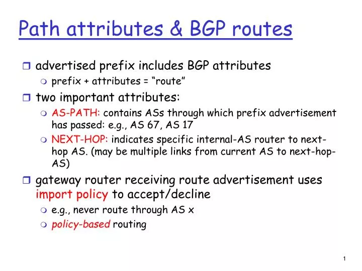
Path attributes & BGP routes. advertised prefix includes BGP attributes prefix + attributes = “route†two important attributes: AS-PATH: contains ASs through which prefix advertisement has passed: e.g., AS 67, AS 17

E N D
Path attributes & BGP routes • advertised prefix includes BGP attributes • prefix + attributes = “route” • two important attributes: • AS-PATH: contains ASs through which prefix advertisement has passed: e.g., AS 67, AS 17 • NEXT-HOP: indicates specific internal-AS router to next-hop AS. (may be multiple links from current AS to next-hop-AS) • gateway router receiving route advertisement uses import policy to accept/decline • e.g., never route through AS x • policy-based routing
BGP route selection • router may learn about more than 1 route to destination AS, selects route based on: • local preference value attribute: policy decision • shortest AS-PATH • closest NEXT-HOP router: hot potato routing • additional criteria
legend: provider B network X W A customer network: C Y BGP routing policy • A,B,C are provider networks • X,W,Y are customer (of provider networks) • X is dual-homed: attached to two networks • X does not want to route from B via X to C • .. so X will not advertise to B a route to C
legend: provider B network X W A customer network: C Y BGP routing policy (2) • A advertises path AW to B • B advertises path BAW to X • Should B advertise path BAW to C? • No way! B gets no “revenue” for routing CBAW since neither W nor C are B’s customers • B wants to force C to route to w via A • B wants to route only to/from its customers!
Why different Intra- and Inter-AS routing ? Policy: • Inter-AS: admin wants control over how its traffic routed, who routes through its net. • Intra-AS: single admin, so no policy decisions needed Scale: • hierarchical routing saves table size, reduced update traffic Performance: • Intra-AS: can focus on performance • Inter-AS: policy may dominate over performance
Next stop: the Data link layer! What we’ve covered: network layer services routing principles: link state and distance vector hierarchical routing IP Internet routing protocols RIP, OSPF, BGP IPv6 Network Layer: summary
Our goals: understand principles behind data link layer services: error detection, correction sharing a broadcast channel: multiple access link layer addressing reliable data transfer, flow control: done! instantiation and implementation of various link layer technologies Chapter 5: The Data Link Layer
5.1 Introduction and services 5.2 Error detection and correction 5.3Multiple access protocols Link Layer
Terminology: hosts and routers are nodes communication channels that connect adjacent nodes along communication path are links wired links wireless links LANs layer-2 packet is a frame,encapsulates datagram Link Layer: Introduction data-link layer has responsibility of transferring datagram from one node to physically adjacent node over a link
datagram transferred by different link protocols over different links: e.g., Ethernet on first link, frame relay on intermediate links, 802.11 on last link each link protocol provides different services e.g., may or may not provide rdt over link transportation analogy trip from Princeton to Lausanne limo: Princeton to JFK plane: JFK to Geneva train: Geneva to Lausanne tourist = datagram transport segment = communication link transportation mode = link layer protocol travel agent = routing algorithm Link layer: context
Link Layer Services • framing, link access: • encapsulate datagram into frame, adding header, trailer • channel access if shared medium • “MAC” addresses used in frame headers to identify source, dest • different from IP address! • reliable delivery between adjacent nodes • we learned how to do this already (chapter 3)! • seldom used on low bit-error link (fiber, some twisted pair) • wireless links: high error rates • Q: why both link-level and end-end reliability?
Link Layer Services (more) • flow control: • pacing between adjacent sending and receiving nodes • error detection: • errors caused by signal attenuation, noise. • receiver detects presence of errors: • signals sender for retransmission or drops frame • error correction: • receiver identifies and corrects bit error(s) without resorting to retransmission • half-duplex and full-duplex • with half duplex, nodes at both ends of link can transmit, but not at same time
in each and every host link layer implemented in “adaptor” (aka network interface card NIC) Ethernet card, PCMCI card, 802.11 card implements link, physical layer attaches into host’s system buses combination of hardware, software, firmware application transport network link link physical Where is the link layer implemented? host schematic cpu memory host bus (e.g., PCI) controller physical transmission network adapter card
sending side: encapsulates datagram in frame adds error checking bits, rdt, flow control, etc. receiving side looks for errors, rdt, flow control, etc extracts datagram, passes to upper layer at receiving side Adaptors Communicating datagram datagram controller controller receiving host sending host datagram frame
5.1 Introduction and services 5.2 Error detection and correction 5.3Multiple access protocols Link Layer
Error Detection • EDC= Error Detection and Correction bits (redundancy) • D = Data protected by error checking, may include header fields • Error detection not 100% reliable! • protocol may miss some errors, but rarely • larger EDC field yields better detection and correction
Parity Checking Two Dimensional Bit Parity: Detect and correct single bit errors Single Bit Parity: Detect single bit errors 0 0
Sender: treat segment contents as sequence of 16-bit integers checksum: addition (1’s complement sum) of segment contents sender puts checksum value into UDP checksum field Receiver: compute checksum of received segment check if computed checksum equals checksum field value: NO - error detected YES - no error detected. But maybe errors nonetheless? Internet checksum Goal: detect “errors” (e.g., flipped bits) in transmitted segment (note: used at transport layer only)
5.1 Introduction and services 5.2 Error detection and correction 5.3Multiple access protocols Link Layer
Multiple Access Links and Protocols Two types of “links”: • point-to-point • PPP for dial-up access • point-to-point link between Ethernet switch and host • broadcast (shared wire or medium) • old-fashioned Ethernet • Shared RF • 802.11 wireless LAN humans at a cocktail party (shared air, acoustical) shared wire (e.g., cabled Ethernet) shared RF (e.g., 802.11 WiFi) shared RF (satellite)
Multiple Access protocols • single shared broadcast channel • two or more simultaneous transmissions by nodes: interference • collision if node receives two or more signals at the same time multiple access protocol • distributed algorithm that determines how nodes share channel, i.e., determine when node can transmit • communication about channel sharing must use channel itself! • no out-of-band channel for coordination
Ideal Multiple Access Protocol Broadcast channel of rate R bps 1. when one node wants to transmit, it can send at rate R. 2. when M nodes want to transmit, each can send at average rate R/M 3. fully decentralized: • no special node to coordinate transmissions • no synchronization of clocks, slots 4. simple
MAC Protocols: a taxonomy Three broad classes: • Channel Partitioning • divide channel into smaller “pieces” (time slots, frequency, code) • allocate piece to node for exclusive use • Random Access • channel not divided, allow collisions • “recover” from collisions • “Taking turns” • nodes take turns, but nodes with more to send can take longer turns
Channel Partitioning MAC protocols: TDMA TDMA: time division multiple access • access to channel in "rounds" • each station gets fixed length slot (length = pkt trans time) in each round • unused slots go idle • example: 6-station LAN, 1,3,4 have pkt, slots 2,5,6 idle 6-slot frame 3 3 4 4 1 1
Channel Partitioning MAC protocols: FDMA FDMA: frequency division multiple access • channel spectrum divided into frequency bands • each station assigned fixed frequency band • unused transmission time in frequency bands go idle • example: 6-station LAN, 1,3,4 have pkt, frequency bands 2,5,6 idle time frequency bands FDM cable
Random Access Protocols • When node has packet to send • transmit at full channel data rate R. • no a priori coordination among nodes • two or more transmitting nodes ➜ “collision”, • random access MAC protocol specifies: • how to detect collisions • how to recover from collisions (e.g., via delayed retransmissions) • Examples of random access MAC protocols: • slotted ALOHA • ALOHA • CSMA, CSMA/CD, CSMA/CA
Assumptions: all frames same size time divided into equal size slots (time to transmit 1 frame) nodes start to transmit only slot beginning nodes are synchronized if 2 or more nodes transmit in slot, all nodes detect collision Operation: when node obtains fresh frame, transmits in next slot if no collision: node can send new frame in next slot if collision: node retransmits frame in each subsequent slot with prob. p until success Slotted ALOHA
Pros single active node can continuously transmit at full rate of channel highly decentralized: only slots in nodes need to be in sync simple Cons collisions, wasting slots idle slots nodes may be able to detect collision in less than time to transmit packet clock synchronization Slotted ALOHA
suppose: N nodes with many frames to send, each transmits in slot with probability p prob that given node has success in a slot = p(1-p)N-1 prob that any node has a success = Np(1-p)N-1 max efficiency: find p* that maximizes Np(1-p)N-1 for many nodes, take limit of Np*(1-p*)N-1 as N goes to infinity, gives: Max efficiency = 1/e = .37 Slotted Aloha efficiency Efficiency : long-run fraction of successful slots (many nodes, all with many frames to send) At best: channel used for useful transmissions 37% of time! !
Pure (unslotted) ALOHA • unslotted Aloha: simpler, no synchronization • when frame first arrives • transmit immediately • collision probability increases: • frame sent at t0 collides with other frames sent in [t0-1,t0+1]
Pure Aloha efficiency P(success by given node) = P(node transmits) . P(no other node transmits in [p0-1,p0] . P(no other node transmits in [p0,p0+1] = p . (1-p)N-1 . (1-p)N-1 = p . (1-p)2(N-1) … choosing optimum p and then letting n -> infty ... = 1/(2e) = .18 even worse than slotted Aloha!