Download
1 / 7
70 likes | 207 Views
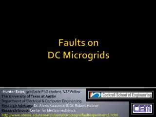
Faults on DC Microgrids. - Hunter Estes , graduate PhD student, NSF Fellow The University of Texas at Austin Department of Electrical & Computer Engineering Research Advisors : Dr. Alexis Kwasinski & Dr. Robert Hebner Research Group : Center for Electromechanics

E N D
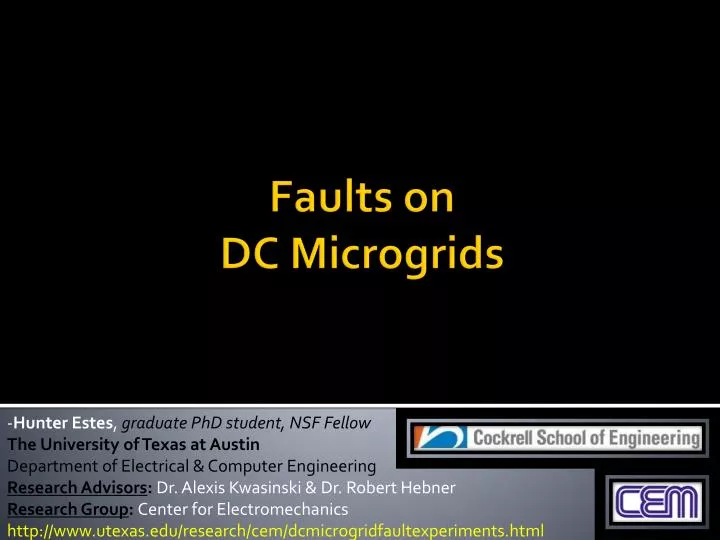
Faults on DC Microgrids -Hunter Estes, graduate PhD student, NSF Fellow The University of Texas at Austin Department of Electrical & Computer Engineering Research Advisors: Dr. Alexis Kwasinski & Dr. Robert Hebner Research Group: Center for Electromechanics http://www.utexas.edu/research/cem/dcmicrogridfaultexperiments.html
Background • The ONR’s next-generation, AES (all-electric ship) platform can be viewed as an isolated microgrid. Many terrestrial microgrids are DC-based, and DC is one of the voltage platforms currently being evaluated by the ESRDC. • While DC microgrids offer many advantages, a prime area of concern relates to faults. Thus, quick fault recognition, identification, and control strategy / fault management are a key research focus. • The end-goal for DC systems is quick fault remediation and/or branch isolation of an affected circuit, while impact on the remaining system (ride through) is minimized. • DC systems will likely need more intelligence built into their system for successful fault management • (i.e. DCsmart grid)
Microgrid Fault Study • A microgrid was constructed in Center for Electromechanics power lab to meet such testing protocol. This will allow for both connected & island-mode operation for the purposes of testing. • The key component of fault testing was the design of a horizontal fault mechanism. This allows for controlled separation or connection through the use of an isolated stepper motor or a pneumatically-driven actuator.
Fault Testing Focus • The focus of this research is to experimentally determine the characteristics of horizontal series & parallel faults in DC systems, and to explore the effects they have in terms of local and system disturbances. • Note: Faults will also be studied in AC systems, as a basis for comparison • Study: DC (280 – 750V) vs. AC systems of “quasi-equivalent” parameters • Monitor:AC & DC fault currents, gap voltages, arc fault transients, power dissipated, bus disturbances, duration, re-strikes, loading effects • Resolution: 50 – 0.5 μs data capture rates, 12 bit resolution • Goals: DC arc modeling, arc fault detection, fault clearing strategies, equipment designs, & safety recommendations
Series Fault Test Results AChoriz. series fault transients DChoriz. series fault transients
DC Parallel Fault Test Results(preliminary) DChorizontal parallel fault transients
Discussion • For series faults, DC systems did not show many fast-acting transients (i.e. spikes) as compared to AC systems. However, DC series faults were an order of magnitude longer in duration, and often damaged electrode structures, locally. • DC series arcing faults are difficult to detect, for their voltages and currents are very similar to pre-arcing conditions. However, equation modeling for dynamic, DC series faults has been accomplished. • AC series faults dissipated within a few cycles from the point of electrode discontinuity. However, re-ignitions were possible. Additionally, fast-acting transients were observed in both the gap voltage and current waveforms. With magnitudes up to four timesthe bus voltage, these spikes may be cause for alarm as this would exceed voltage ratings for various passive components within system power electronics. • DC parallel faults seem to show some disturbances at lower levels. However, testing will continue to higher thresholds to observe such effects in more detail. These will also be compared to AC systems.