Download
1 / 21
210 likes | 221 Views
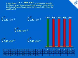
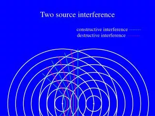
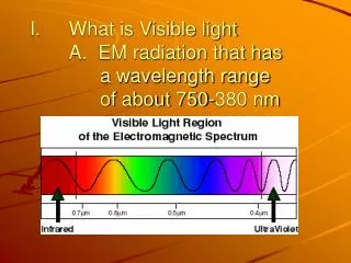
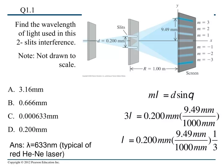
Q1.1. Find the wavelength of light used in this 2- slits interference. Note: Not drawn to scale. 3.16mm 0.666mm 0.000633mm 0.200mm. Ans: λ=633nm (typical of red He-Ne laser). Phasor review. Will need phasors to understand diffraction gratings.

E N D
Q1.1 Find the wavelength of light used in this 2- slits interference. Note: Not drawn to scale. • 3.16mm • 0.666mm • 0.000633mm • 0.200mm Ans: λ=633nm (typical of red He-Ne laser)
Phasor review Will need phasors to understand diffraction gratings.
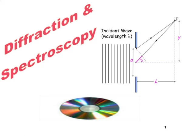
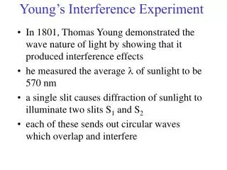
Diffraction grating and the sun (first gateway to QM) Joseph von Fraunhofer (1787-1826) Unexpected dark lines due to the absorption of elements in the sun’s atmosphere. In the 20th century it was realized that atomic energies are quantized. The spectrum is not continuous !
Crystallography by X-ray diffraction Protein x-ray crystallography setup at the SLAC LCLS (Linac Coherent Light Source) in Stanford, CA. First x-ray diffraction image of DNA by Rosalind Franklin (Fig 36.24 of the text) Other similar facilities in Hamburg Germany and Harima Science City, Japan
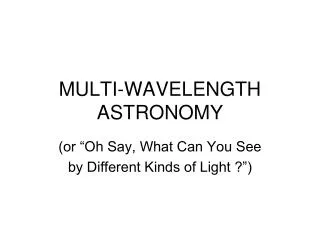
Goals for Chapter 36 (Diffraction) • To see how a sharp edge or an aperture affect light • To analyze single-slit diffraction and calculate the intensity of the light • To investigate the effect on light of many closely spaced slits • To learn how scientists use diffraction gratings (e.g. in astrophysics) • To see what x-ray diffraction tells us about crystals, proteins… • To learn how diffraction places limits on the resolution of a telescope • Holograms !
Diffraction, Chapter 36 What is Diffraction: the process by which a beam of light or other system of waves is spread out as a result of passing through a narrow aperture or across an edge, typically accompanied by interference between the wave forms produced. A picture helps Diffraction of water waves
Diffraction from a single slit (Physical Optics) • In the Figure below, the prediction of geometric optics in (a) does not occur. Instead, a diffraction pattern is produced, as in (b). • The narrower the slit, the broader the diffraction pattern. • Light is a wave (EM waves) and hence diffracts. • Diffraction phenomena also occur for EM waves, sound, electrons (QM) Geometric optics Physical Optics
Diffraction What physical parameters control whether single slit diffraction occurs ? Ans: λ (wavelength), a (slit spacing). But this is not the full story. Ans: 2nd part, distance to the screen (near field, Fresnel diffraction) and (far field, Fraunhofer diffraction)
Diffraction • According to geometric optics, a light source shining on an object in front of a screen should cast a sharp shadow. Surprisingly, this does not occur because of diffraction.
Diffraction and Huygen’s Principle • Huygens’s principle can be used to analyze diffraction. • Fresnel diffraction: Source, screen, and obstacle are close together. • Fraunhofer diffraction: Source, screen, and obstacle are far apart. • The figure below shows the diffraction pattern of a razor blade.
Diffraction and Huygen’s Principle • What is Huygens’s principle ? The Huygens-Fresnel principle states that every point on a wavefront is a source of wavelets. These wavelets spread out in the forward direction, at the same speed as the source wave. The new wavefront is a line tangent to all of the wavelets. So what is interfering in single slit diffraction ?
Fresnel and Fraunhofer diffraction by a single slit • The figure below shows Fresnel (near-field) and Frauenhofer (far-field) diffraction for a single slit.
Locating the dark fringes • Review the single-slit diffraction discussion in the text. • The figure below shows the geometry for single slit Fraunhofer diffraction. (Imagine the aperture is made of many tiny slits). What is the path difference between the two strips ? Ans: path difference =a/2 sin(θ) Dark fringe If path difference to P is λ/2, what do we see at Point P ?
Locating the dark fringes in single slit diffraction In general, at what angles do we find the dark fringes ? Ans: If path difference to P is mλ/2, we will find dark fringes Dark fringes
Locating the dark fringes in the single slit diffraction pattern
Examples of single-slit diffraction • The figure on the left is a photograph of a Fraunhofer pattern of a single horizontal slit. What features are especially notable ? • Example 36.1: You pass 633-nm light through a narrow slit and observe the diffraction pattern on a screen 6.0 m away. The distance at the screen between the center and the first minima on either side is 32 mm long. How wide is the slit?
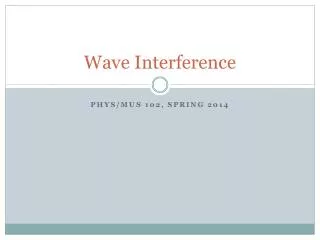
Intensity in the single-slit pattern • Follow the text’s discussion of the intensity in the single-slit pattern using the phasor diagrams below.
Quantitative Intensity in the single-slit pattern • The angle b is the phase angle of the ray from the top of the slit, while the phase angle from the bottom of the slit is 0. The vectors lie along a circle whose center is at C, so Ep is a chord of the circle. The arc length E0 is subtended by this same angle b, so the radius of the circle is E0/b. • From the diagram, • Since • We have (sinc function)
Quantitative Intensity in the single-slit diffraction pattern Intensity of a single slit diffraction pattern
Intensity maxima in a single-slit pattern • The figure on the right shows the intensity versus angle in a single-slit diffraction pattern. • The minima occur when β is a multiple of 2π, i.e. at • The location of the maxima are found by taking the derivative of • and setting it to zero. Surprisingly, these are not precisely where • In fact, there are no maxima for m = 0 in this expression. The central maximum is wider than the others, and occurs at q = 0. • Using these approximate values of β in the intensity, we find
Width of the single-slit pattern • The width of the single-slit diffraction pattern depends on the ratio of the slit width a to the wavelength λ.