Download
1 / 83
1.01k likes | 1.91k Views
NCODP MK 19, 40-MM GRENADE MACHINE GUN. CREED OF THE NONCOMMISSIONED OFFICER.

E N D
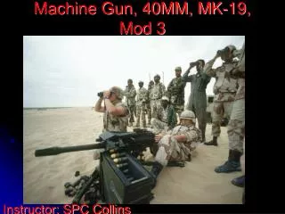
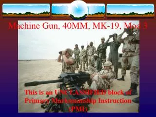
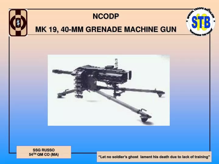
NCODP MK 19, 40-MM GRENADE MACHINE GUN
CREED OF THE NONCOMMISSIONED OFFICER NO ONE IS MORE PROFESSIONAL THAN I. I AM A NONCOMMISSIONED OFFICER, A LEADER OF SODLEIRS. AS A NONCOMISSIONED OFFICER I REALIZE THAT I AM A MEMBER OF A TIME HONORED CORE WHICH IS KNOWN AS THE BACKBONE OF THE ARMY. I AM PROUD OF THE COURE OF NONCOMMISSIONED OFFICERS, AND WILL AT ALL TIMES CONDUCT MYSELF SO AS TO BRING CREDIT UPON THE CORPS, THE MILITARY SERVICE, AND MY COUNTRY REGARDLESS OF THE SITUATION IN WHICH I FIND MYSELF. I WILL NOT USE MY GRADE OR POSITION TO ATTAIN PLEASURE, PROFIT OR PERSONAL SAFETY. COMPETENCE IS MY WATCHWORD. MY TWO BASIC RESPONSIBILITIES WILL ALWAYS BE UPPERMOST IN MY MIND-ACCOMPLISHMENT OF MY MISSION AND THE WELFARE OF MY SOLDIERS. I WILL STRIVE TO REMAIN TECHNICALLY AND TACTICALLY PROFICIENT. I AM WARE OF MY ROLE AS A NONCOMMISSIONED OFFICER. I WILL FULFILL MY RESPONSIBILITIES INHERENT IN THAT ROLL. ALL SOLDIERS ARE ENTITLED TO OUTSTANDING LEADERSHIP; I WILL PROVIDE THAT LEADERSHIP. I KNOW MY SOLDIERS AND I WILL ALWAYS PLACE THEIR NEEDS ABOVE MY OWN. I WILL COMMUNICATE CONSISTENTLY WITH MY SOLDIERS AND NEVER LEAVE THEM UNINFORMED. I WILL BE FAIR AND IMPARTIAL WHEN RECOMMENDING BOTH REWARD AND PUNISHMENT. OFFICERS OF MY UNIT WILL HAVE MAXIMUM TIME TO ACCOMPLISH THEIR DUTIES; THEY WILL NOT HAVE TO ACCOMPLISH MINE. I WILL EARN THEIR RESPECT AND CONFIDENCE AS WELL AS THOSE OF MY SOLDIERS. I WILL BE LOYAL TO THOSE WITH WHOM I SERVE; SENIORS, PEERS, AND SUBORDINATES ALIKE. I WILL EXERCISE INITIATIVE BY TAKING APPROPRIATE ACTION IN THE ABSENCE OF ORDERS. I WILL NOT COMPROMISE MY INTEGRITY NOR MY MORAL COURAGE. I WILL NOT FORGET, NOR WILL I ALLOW MY COMRADES TO FORGET THAT WE ARE PROFESSIONALS, NONCOMMISSIONED OFFICERS, LEADERS!
TASK CONDITIONS AND STANDARDS TASK TO CONDUCT NONCOMMISSIONED OFFICER PROFESSIONAL DEVELOPMENTGOVERNING THE MK 19, 40-MM GRENADE MACHINE GUN, MOD 3 CONDITIONS GIVEN THE NONCOMMISSIONED OFFICERS OF THE CONSOLIDATED 49TH SPECIAL TROOPS BATTALION, A CLASSROOM ENVIRONMENT, AND ALL NECESSASRY MATERIALS, REVIEW THE APPLICATION, OPERATION AND FUNCION, PMCS, CREW DRILLS, EMPLACEMENT, ZEROING, MARKSMANSHIP, RANGE CARD, APPLICATION AND TECHNIQUES OF FIRE, AND CORRECTIVE FEEDING ACTION (FM 23-27, PS 578) STANDARDS TO FAITHFULLY EXCECUTE THE DUTIES AND RESPONSIBILITIES INHERENT IN THE ROLES OF THE NONCOMMISSIONED OFFICER IN THE LEADING AND TRAINING OF SOLDIERS ASSIGNED TO THE MK 19
RISK ASSESSMENT TASK ID HAZARDS ASSESS HAZARDS DEVELOP CONTROLS RES RISK IMPLEMENT CONTROLS POSTED FIRE PLAN SEE NEXT SLIDE NCOPD FIRE L L TRIPPING HAZARD L MINIMIZE WIRES IN WALKWAYS L AVOID WIRES ON FLOOR LEADING TO OUTLETS L L THREATCON IDENTIFY SUSPICIOUS INDIVIDUALS ENTERING BUILDING REPORT ANY SUSPECIOUS INDIVIDUALS ATTEMPTING TO ENTER THE 240TH CLASSROOM
EXIT EXIT EXIT FORMATION AND ACCOUNTABILITY FIRE PLAN
AGENDA • CREED OF THE NONCOMMISSIONED OFFICER • TASK CONDITIONS AND STANDARDS • RISK ASSESSMENT • FIRE PLAN • AGENDA • DUTIES, RESPONSIBILITIES • HISTORY OF THE MK 19 • INTRODUCTION • OPERATION AND FUNCTION • CREW DRILLS • MARKSMANSHIP FIRING POSITIONS • TRAVERSING BAR AND T&E MECHANISM • SIGHTING AND AIMING • RANGE CARD • ANNUAL GUNNERY TRAINING PROGRAM • SUMMARY • QUESTIONS
DUTIES AND RESPONSIBILITES WHY ARE NCO’S RECEIVING NCOPD ON A WEAPON SYSTEM THAT WILL NOT BE OUR ASSIGNED WEAPON? • WE ARE LEADERS! If our soldier’s are tasked to operate this piece of equipment, we must be proficient enough to train them on this piece of equipment! • BE, KNOW, DO! If we are to “BE” a leader of soldiers, we need to “KNOW” how to operate this piece of equipment, clear malfunctions, train soldiers on its use, PMCS, clear malfunctions, set emplacements, dig fighting positions, give fire commands, determine sectors, complete range card…. We must be able to “DO” all of the above in order to lead by example—we can’t tell a soldier to perform a task we cannot perform ourselves!
Development began in 1963 with a preliminary version that was a hand cranked grenade launcher called the MK 18. In 1966 the MK 19 Mod 0 was developed, however the MOD 0 was not reliable or safe to be placed in the Army’s inventory. Improvements in 1971 led to the Navy’s adoption of the MOD 1 in 1972 and worked well during the Vietnam conflict. In 1976, the weapon was redesigned as the MK 19 MOD 3, that was adopted for Army use in 1983. The Army has expanded the use of the MK 19 for tactical defense, retrograde, patrolling, rear area security, MOUT, and Spec Ops. HISTORY OF THE MK 19
INTRODUCTION • THE MK 19 SUPPORTS THE SOLDIER IN BOTH THE OFFENSE AND DEFENSE. IT GIVES THE UNIT A HEAVY VOLUME OF CLOSE, ACCURATE, AND CONTINUOUS FIRE. IT CAN ALSO BE USED TO— • Protect motor movements, assembly areas and supply trains • Defend against hovering rotary aircraft • Destroy lightly armored vehicles • Fire on suspected enemy positions • Provide high volumes of fire into an engagement area • Cover obstacles • Provide indirect fires from defilade positions.
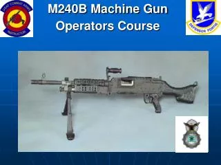
INTRODUCTION The MK 19 is an air-cooled, blowback-operated machine gun, with five major assemblies that is belt-fed through the left side of the weapon by a disintegrating metallic link belt.
INTRODUCTION Leaf type rear sight mounted on a spring dovetail base, which should be folded forward to a horizontal position when the weapon is moved; the range increment of 100 meters from 300 to 1500m. Range changes by slide release or the elevation wheel: slide release for major changes in elevation; slide wheel for fine adjustments. Rear sight adjusts for windage, turning the windage screws right or left equals a 1-mil change.
INTRODUCTION The HEDP (High Explosive, dual purpose) M430 cartridge, joined with M16A2 links is the standard round for the MK 19. The impact-type round penetrates 2 inches of steel armor at a 0-degree obliquity and inflicts personnel casualties in the target area. The two HE (High Explosive) cartridges inflict personnel casualties in the target area with ground burst effects. HE M383 and M383E1 are packed 50 per box. The M385 practice rounds are joined by M16A1 or M16A2 links in 50 rounds per box. M992 dummy cartridges are joined with M16A2 links with a 10 round belt used to check weapon function for crew training.
OPERATION AND FUNCTION NOTE: CLEARING IS DIFFERENT BETWEEN FIRING AND NONFIRING SITUATIONS! • Firing Situation: • Move safety switch to SAFE (“S”). If all of the ammunition has NOT been fired, the bolt is to the rear and a round is on the bolt face. • Open the top cover assembly. • Take the ammo from the feed tray by reaching beneath the feed tray and pressing the primary and secondary positioning pawls. At the same time slide the linked rounds out of the MK 19 through the feed throat.
OPERATION AND FUNCTION (4) Insert a section of the cleaning rod or bayonet through either side of the receiver rail. Place it on top of the live round or cartridge case, as close to the bolt face as possible, and push down, this action forces the round out of the MK 19—use extreme caution and catch round with hand—do not allow it to hit the ground! (5) Lower and pull charging handle to the rear.
OPERATION AND FUNCTION (6) Inspect the chamber and bolt face again to insure that no live rounds are in the weapon. (7) Place the safety switch on FIRE (“F”). (8) While maintaining rearward pressure on the charging handle, press the trigger and ease the bolt forward. (9) Place the safety switch on SAFE (“S”).
OPERATION AND FUNCTION • Nonfiring Situation: • Place the safety switch on SAFE. • Open the top cover assembly. • Lower one charger handle. • Pull the charger handle slightly to the rear, allowing sufficient space between the face of the bold and the chamber to see both (Check for ammo). • Ride the bolt forward. • Return charging handle to its original upright position.
OPERATION AND FUNCTION • Disassembly: • Clear the Weapon • Take out the secondary drive lever: • (a) Raise the top cover assembly and push the secondary drive lever pivot post from the outside of the top cover assembly. Separate the secondary drive lever from the top cover assembly.
OPERATION AND FUNCTION (b) Take the secondary drive lever from the slide assembly, and allow the feed slide and tray assembly to close. (3) Take off the top cover assembly. Hold it straight up with one hand and pull the top cover pins from both sides. Lift the top cover assembly straight up and off.
OPERATION AND FUNCTION (4) Take out the feed slide assembly and feed tray: (a) Alight the tabs on the feed slide assembly with the slots in the feed tray and lift them straight up. (b) Take out the feed tray by lifting straight up.
OPERATION AND FUNCTION (5) Take out the bold and backplate assembly: (a) Place the safety switch to the FIRE position. (b) Take out the backplate pin using the rim of a spent cartridge case or metal link. Pry outward on the pin lip and remove the pin with the fingers.
OPERATION AND FUNCTION (c) Grasp control grips with both hands and lift up slightly to disengage the backplate from the locking lugs in the receiver. Pull the bolt and backplate assembly to the rear. Once the bolt clears the sear, catch the bolt in one hand to prevent damage to he backplate assembly.
OPERATION AND FUNCTION (6) Take off the primary drive lever and vertical cam: (a) Reach under the top of the receiver and locate the drive lever lock. Slide the lock a quarter inch to the rear. (b) Press down on the primary drive lever pivot post, which releases both the primary drive and vertical cam. (C) Pull the primary drive lever from the front of the weapon and the vertical cam from the back.
OPERATION AND FUNCTION (7) Take off the sear assembly: (a) Turn the MK 19 on its side or upside down and use the rim of a spent cartridge case to lift the sear lock plunger. At the same time squeeze the sear and rotate the assembly 90 degrees to the right (or left). Take off the sear assembly by pulling it away from the weapon. Keep pressure on the sear until the assembly comes off. Switch to SAFE.
OPERATION AND FUNCTION (8) Take off the alignment guide: (a) Depress the tip of the alignment guide spring with the finger. (b) Slide the alignment guide out of the receiver, pulling the assembly slightly rearward.
OPERATION AND FUNCTION (9) Take out the ogive plunger, by pulling the ogive plunger assembly out through the inside wall of the receiver.
OPERATION AND FUNCTION (10) Take off the round-positioning block by pushing it into the side of the gun, sliding it forward and releasing it from the keyslots in the receiver wall.
OPERATION AND FUNCTION (11) Take out the charger assemblies from both sides. Place the charger assemblies in the upright position. Using a metallic object, retract the lock plunger at the base of the charger arm. Slide the charger housing rearward to disengage the lugs from the keyslots in the receiver. Lift the charger assembly away from the receiver.
OPERATION AND FUNCTION • To assemble the gun, replace the groups in reverse order: • Replace charger assemblies • Replace the round-positioning block • Replace the ogive plunger • Replace the alignment guide • Replace the primary drive lever and vertical cam • Attach the sear assembly: depress the sear spring and turn assembly 90º toward barrel center line until locks into position • Insert the bolt and backplate assembly • (a) Ensure the cocking lever is forward and insert the bolt and backplate assembly into the receiver.
OPERATION AND FUNCTION NOTE: Before inserting the assembly, place the cocking lever in the forward position. Ensure that the safety switch is on FIRE so the sear can easily be depressed. (b) Press the receiver sear and slide the bolt assembly forward until the retainer pin holes in the backplate and receiver are aligned.
OPERATION AND FUNCTION (c) Insert the backplate retainer pin to lock the assembly into position. (8) Place the feed tray assembly on the receiver. Place the feed slide assembly into the cutout slots on the feed tray. (9) Attach the top cover assembly: (a) Align the pinholes in the top cover assembly with the pinholes in the feed tray. (b) Hold the cover straight up and insert the pins into both sides of the cover. (10) Replace the secondary driver lever: (a) Lift the feed slide assembly and feed tray.
OPERATION AND FUNCTION (b) Place the forked end of the secondary drive lever on the inner feed slide pin. (c) Press the raised pivot post through the hole in the top cover assembly. Press the secondary drive lever firmly against the top cover assembly.
BREAK AT THIS TIME, TAKE A 10 MINUTE BREAK. BE BACK AND READY TO RESUME INSTRUCTION AT THE END OF 10 MINUTES!
OPERATION AND FUNCTION LOADING Ensure the weapon is on SAFE, the bolt in the forward position, and the feed throat is attached to the weapon and is pointing in a downward direction.
OPERATION AND FUNCTION (1) Insert the first round into the feeder (female link first). (2) Push the round across the secondary feed pawl. To move the feed slide assembly to the left, push the secondary drive lever to the right and close the cover.
OPERATION AND FUNCTION (3) Grasp the charger handles with the palms down. Press in on the charger handle locks. Rotate the handles down and pull them sharply to the rear (A). After locking the bolt to the rear, return the charger handles to their original upright position (B).
OPERATION AND FUNCTION (4) Place the safety switch on FIRE and press the trigger. The bolt slams forward and grasps the first round in the bolt extractors. (5) Grasp, unlock and turn downward the charging handles to their original upright position. (6) Ensure the safety switch is on SAFE. (7) Return the charger handles to their original upright position. (8) The MK 19 is ready to fire.
OPERATION AND FUNCTION • Precautions: • Ensure the top cover is closed • Ensure the muzzle of the MK 19 is pointed downrange at all times. In the event of a runaway gun, lower one of the charging handles. • Use the suggested three-to five-round bursts. • After firing: • Unload and clear • Perform after PMCS and report deficiencies to the armorer • Clean and lubricate the MK 19 before storage
OPERATION AND FUNCTION Malfunctions and corrections: NOTE: Defective ammo nor soldier head-space-and-timing is considered a weapon malfunction. The two malfunctions are “sluggish gun,” and “runaway gun.” Sluggish Gun: Caused by excessive friction from dirt, carbon build-up, lack of lubrication, or burred parts. Conduct a proper PMCS, replace worn and or damaged parts, as necessary. Runaway Gun: Weapon continues to fire after the trigger has been released. Caused by worn parts or short recoil of the bolt assembly. If ammo is not low and gun is in the free mode, keep rounds on target until all the rounds on the belt have been fired. If mounted on tripod with T&E, hold the grip with one hand, press the charger handle locks and lower one charging handle. This interrupts the cycle causing the weapon to cease firing.
OPERATION AND FUNCTION IMMEDIATE ACTION: In the event of a stoppage in the MK 19, take immediate action: recharge it and try to fire once. REMEDIAL ACTION: A stoppage is any interruption in the cycle of operation caused by faulty action of the weapon or ammunition. Take remedial action if immediate action does not end the stoppage. (1) Unload and clear MK 19. (2) Inspect the weapon and ammo to find the cause of stoppage. CORRECTIVE ACTION: Take corrective action to correct the stoppage one the cause has been found. If possible, correct the cause of the stoppage, reload and try to fire the weapon. If it still does not fire, or cannot be repaired at the operator level contact the unit armorer.
CREW DRILLS Crew drills build precision, speed, skill and teamwork in checking equipment, placing the MK 19 into and taking it out of action, and moving it to a new position. Precision—the main goal– is achieved by following prescribed procedures. Speed, skill, and teamwork grow with practice. During the crew drill, all oral and visual signals are repeated. Once crew members can perform their duties well, they rotate to allow each member of the crew to learn the duties of the others. The ground mounted MK 19 has three crew members: the gunner, the assistant gunner, and the ammo bearer. A vehicle assigned to the crew carries the ammo and equipment to the firing position. The terrain and enemy situation dictate how close the vehicle may be brought to the firing position. To assist your soldiers, you may follow the step by step guidelines found in Chapter 4, of FM 23-27
CREW DRILLS Leader Command: “FORM FOR CREW DRILL” TASK Participate as MK 19 Crew member in the crew drill formation CONDITION In a classroom environment, given a MK 19 gunner, assistant gunner, ammo bearer, the weapon system, ammo, and the command, FORM CREW DRILL STANDARD Upon hearing the leader’s command, the crew forms in a column, five paces apart, in the following order: Assistant gunner, gunner, and ammo bearer.