Download
1 / 40
420 likes | 611 Views
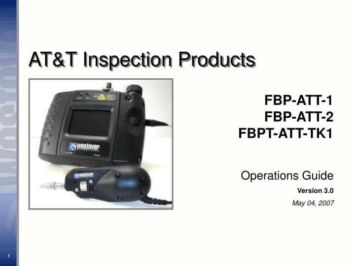
AT&T Inspection Products. FBP-ATT-1 FBP-ATT-2 FBPT-ATT-TK1. Operations Guide Version 3.0 May 04, 2007. Agenda. Fiber Basics Equipment Overview Fiber Inspection Fiber Grading Maintenance Kits.

E N D
AT&T Inspection Products FBP-ATT-1 FBP-ATT-2 FBPT-ATT-TK1 Operations Guide Version 3.0 May 04, 2007
Agenda • Fiber Basics • Equipment Overview • Fiber Inspection • Fiber Grading • Maintenance • Kits Note: For additional information about Westover equipment as it pertains to AT&T processes & procedures please reference the following Apex document: ATT-TELCO-002-200-381 “Construction FWG LFO-In SSIM I&R Outside Plant: Fiber Optic Connector & Adapter Inspection and Cleaning Tools & Procedures”
Ferrule Fiber Body Fiber Basics: Connectors Body The connector body holds the ferrule and holds the fiber in place Ferrule Thin cylinder where the fiber is mounted; acts as the fiber alignment mechanism; the end of the fiber is located at the end of the ferrule Fiber • Cladding Optical fiber layer (lower refractive index) that has direct contact with the Core layer. Typically 125μ in diameter. • Core The critical center layer of the fiber (total internal reflection) where light passes through. Typically 9μ for singlemode fiber. LC Connector Core Singlemode (9μ) Cladding (125μ) Microscope /Display View
Why Inspect? Dirt & Contamination • Contamination is the number one cause of troubleshooting in optical networks • Contaminated connectors that are mated cause embedded debris and pits, which are permanent forms of damage • Contamination must be removed prior to mating connectors Clean Dirt Pit
Inspect before you connect! Note: For specific information regarding the AT&T cleaning procedures, please reference ATT-TELCO-002-200-381
Inspect Both Sides Two Types of Inspection Patch Cord Inspection The HD2 Display has a microscope for patch cord inspection built into the device. Bulkhead Inspection Attaching the Probe microscope to the display enables inspection of fiber end-faces within a bulkhead.
Troubleshooting & Maintenance Component Mfg. System Test Installation System Assembly Receiving & QC Network Test Where Inspection Occurs Inspection of fiber end-faces is critical at EVERY STAGE of handling fiber!
Equipment Overview Westover Fiber Inspection Microscopes are used for visual end-face inspection of fiber optic connectivity. Integrated Visual Fault Locator (VFL) Change adapters to match connector being inspected Built-in Patch Cord Microscope 3.5” LCD Video display Dual (200X & 400X) mag. Probe inspects through bulkheads Built-In coaxial illumination (100,000 hour life) Ergonomic design easily fits in hand Change tips to match connector being inspected
HD2 Display Overview The HD2 Display is a compact and ergonomic multi-functional display with a 3.5” TFT LCD screen with a rugged design suitable for use indoors and outdoors. • Features • Ruggedized, drop tested enclosure • 3.5” TFT LCD display • P5 Probe input • Patch cord viewer • Visual Fault Locator (VFL) • Removable battery pack (8 “AA” batteries) • Power saving Grip Switch • Low battery warning LED • AC adapter (power supply 110V/12VDC). • Brightness control • Socket for ¼-20 UNC Tripod mount
HD2 Display Battery Installation 1 2 3 Note: The NiMH rechargeable batterieswill not and cannot be recharged inside the HD2 Display. They must be removed from the tray and charged with the included battery charger. • Insert 8 fully charged “AA” batteries into the battery pack • Align the ‘positive’ and ‘negative’ ends (contacts) on the bottom of the battery tray to their respective ends inside the HD2 Display and insert the tray into the compartment on the top left-hand side of the display • Attach the cover to securely lock and conceal the battery pack Power & Charging the Batteries The HD2 display can also be powered by attaching the 110V/12VDC Power Supply Once the batteries are too low in power, the screen will turn off and the Low Bat indicator will illuminate.
HD2 Display: Power Switch Power-On Mode • Switch the power setting to the On mode • The green LED indicator will illuminate next to “Power” at the bottom of the display Front View Side View
HD2 Display: Power Switch Grip Switch Mode: This setting is used to maximize battery life • Switching to “Grip” Mode activates a pressure-sensitive Grip Switch at the back of the unit. • In the Grip mode power can be turned On or Off as pressure is applied and released Grip Switch 1 2
HD2 Display Brightness Control, Tripod Socket, Table Stand & Hanger 1. Brightness Control 3. Table Stand 2. Tripod Socket 4. Hanging Accessory • Brightness Control: Adjusts the brightness of the display screen with the aperture wheel • Tripod Socket: Allows the display to be mounted on tripod stands for hands-free operation • Table Stand: Position the display on flat surfaces for hands-free operation • Hanging Accessory: Hand the display where suitable for hands-free operation
Patch Cord Module (integrated microscope) To use the integrated microscope (patch cord-view)… • Select the appropriate patch cord adapter from the three listed on the next page and install onto the patch cord module • Insert/attach the patch cord into the adapter on the patch cord module input • Use the Power Selector to select either “On” or “Grip” • Verify that the internal patch cord microscope is selected (the A/B LED which is controlled by pushing the “A/B” button should be illuminated) • Use the Focus wheel to adjust the focus on the fiber end image • If the FMAE-MTPA MPO is used: Steps 1 & 2 Step 4 Step 5 SmallPanning Knob FMAE-MTPA MPO • The “Large” Panning Knob on the MPO adapter should be facing front, aligned vertically with the “A/B” button and set in a fixed position • Use the “Small” Panning Knob to adjust/center the fibers vertically on the display • Use the “Large” Panning Knob to pan across the connector to view the fibers individually Large Panning Knob
FMAE-U25Universal 2.5mm adapter FMAE-U12Universal 1.25mm adapter FMAE-MTPAMPO (angled) adapter Patch Cord Module Adapters Overview The various adapters are interchangeable on the Patch Cord module of the HD2 Display, allowing inspection of different types of fiber optic connectors.
P5 Probe Microscope Overview The P5 Probe Microscope incorporates an imaging system, integrated light source, video camera, focus mechanism, magnification control and connector-specific tips. The P5 Probe Microscope can be used to inspect both sides of an optical interconnect. Focus Wheel used to adjust focus on the display screen Dust Cap remove before attaching probe tips 4-pin Connector ensures a secure and firm latch-lock connection with the HD2 display Magnification Control used to adjust between “low” and “high” magnification settings
P5 Probe Microscope Connecting the Probe and Display 1 2 3 • Locate the “female” connection on the right-hand side of the display unit • Align the notch-key configuration of the “male” end of the probe microscope to the “female” end of the display unit and attach • Secure by tightening the screw
Inspection Tip Configuration Bulkhead Tips: Long Reach Bulkhead Tips: 60° Angled Patchcord Tips Barrel Assembly Bulkhead Tips: Standard Bulkhead Tips: Ribbon Connectors
Bulkhead Inspection Tips Simplex Inspection Tips • Bulkhead tips can inspect simplex connectors located behind a bulkhead • 60° angled tip can inspect connectors located in tight, hard-to-reach areas SC Bulkhead Tip Angled 60○ FBPT-SC-A6 Barrel Assembly FBPP-BAP1 SC Bulkhead Tip FBPT-SC Simplex Fiber View
Bulkhead Inspection Tips RibbonDrive™ Inspection Tips • Provide stable and repeatable inspection of all fibers on the ribbon ferrule endface • Provide inspection of high density, multi fiber array connectors mounted within a bulkhead adapter. • Panning knob allows the user to view each fiber in a liner array. MTP APC Bulkhead Inspection Tip Extra Long Reach FBPT-MTPA-XL Ribbon Fiber View
Bulkhead Adapters Overview Within each kit are 3 bulkhead adapters to compliment the 3 probe tips (LC, SC, MPO). These adapters can be used in conjunction with the probe tips to inspect patch cords at both low and high magnification settings. LC Patch Cord Inspection SC MPO
Visual Fault Locator (VFL) Overview The integrated Visual Fault Locator (VFL) module employs a powerful red laser designed to couple to optical connectors, giving you the ability to locate damaged or broken optical fibers. Step 1 Step 3 Step 4 • Insert the connector (SC Connector shown) into the VFL input located on the top of the display • Press the On/Off button to activate the VFL • The red LED indicator (next to Power) will illuminate when the VFL is active • Press the Flash button to activate the flashing-mode Step 2 Illumination indicating damage or break Note: The VFL is equipped with a 2.5mm interface. Converters for other ferrule types such as 1.25mm are available from Westover Scientific. Another method for interface conversion includes using a hybrid patch cord and adapter.
Fiber Inspection Procedures Simplex Patch Cords • Switch/toggle the “A/B” button to turn the patch cord module ON (red indicator). • Remove the dust cap from the patch cord and place in an anti-static (ESD-sensitive) bag (save/secure the dust cap for later use). • Insert the patch cord into the patch cord module and focus the image to inspect. • Focus Image w/ Focus Wheel Note: It is essential to implement Electrostatic Discharge (ESD) preventive measures (such as using anti-static bags and wristbands) when working with ESD-sensitive equipment.
Inspection Procedures Bulkhead Adapters (Simplex Connectors) INSPECT (SC & LC) • Select the appropriate probe tip and patch cord adapter that match the connector and attach them to the system. • Remove the dust cap from the bulkhead adapter and place in an anti-static (ESD-sensitive) bag (save/secure the dust cap for later use). • Inspect the connector within the bulkhead. Note: It is essential to implement Electrostatic Discharge (ESD) preventive measures (such as using anti-static bags and wristbands) when working with ESD-sensitive equipment.
Inspection Procedures Ribbon Patch Cords • Switch/toggle the “A/B” button to turn the patch cord module ON (red indicator). • Attach the MPO APC Patch Cord Adapter to the patch cord module Remove the dust cap from the patch cord and place in an anti-static (ESD-sensitive) bag (save/secure the dust cap for later use). • Insert the patch cord into the patch cord module and focus the image to inspect. • Use the “Small” and “Large” Panning Knobs on the MPO adapter to adjust the display image vertically and to pan horizontally across the fiber ribbon array, respectively. MPO APC Adapter Panning Knobs Note: It is essential to implement Electrostatic Discharge (ESD) preventive measures (such as using anti-static bags and wristbands) when working with ESD-sensitive equipment.
Inspection Procedures Bulkhead Inspection (Ribbon Connectors) • Select the MPO bulkhead tip and attach to the probe. • Remove the dust cap from the bulkhead adapter and place in an anti-static (ESD-sensitive) bag (save/secure the dust cap for later use). • Inspect the MPO connector behind the bulkhead. • Use the Panning Knob on the MPO probe tip to view each fiber across the ribbon array. Panning Knob Note: It is essential to implement Electrostatic Discharge (ESD) preventive measures (such as using anti-static bags and wristbands) when working with ESD-sensitive equipment.
Cleaning Tools Note: AT&T has recently updated cleaning procedures by transition away from using swabs for bulkhead cleaning. The new procedures involve use of the tools shown below. Further details on these procedures can be found in ATT-TELCO-002-200-381 CLEANER FIBER OPTIC MPO (PID 310095690) Used for cleaning the ferrule end faces of MPO connectors. This device cleans all 12 fibers at once. Capable of cleaning ferrules with or without guide pins. Cleaning count: 500 FERRULE MATE SFM-250 (PID 310111984) Used for cleaning the ferrule end faces of 2.5mm simplex fiber connectors (ex: SC, ST, FC). Cleaning count: 350 FERRULE MATE SFM-125 (PID 310111992) Used for cleaning the ferrule end faces of 1.25mm simplex fiber connectors (ex: LC). Cleaning count: 350
Inspect before you connect! Note: For specific information regarding the AT&T cleaning procedures, please reference ATT-TELCO-002-200-381
Grading Fiber: Pass Fail Criteria Dirt & Defects Pass/Fail criteria for AT&T can be found in the following section of ATT-TELCO-002-200-381: The Universal Grading Template is only used when there is a defect that can not be removed in the cleaning process described in ATT-TELCO-002-200-381
Grading Fiber: Pass Fail Criteria Dirt & Defects • Identify the debris and defects which can not be removed • To grade these defects, place the template over the fiber on the “low” side • Use the “Keys to Zone” section of the template to determine in which zone the identified defects are located • Use the reference dots on the template to identify the size of the defects • Refer to the appropriate table for Pass/Fail Criteria in ATT-TELCO-0020200-381
Grading Fiber: Pass / Fail Criteria • The following Pass/Fail criteria can be found in ATT-TELCO-002-200-381 • Suggestion: Keep this criteria readily available when inspecting (print and keep in kit with grading guide).
Maintenance Contamination • In general, this kit requires little or no maintenance. However, there are issues that can arise and it’s important to know how to recognize when the unit needs service. • If the optical system becomes contaminated, it can degrade the image quality. There are 3 symptoms of this condition: • Camera Sensor Contamination • Lens Contamination • Tip Contamination Note: All service work is performed at Westover Scientific’s factory just outside Seattle, Washington.
Camera Sensor Contamination • This sort of contamination will show as a black spot. These spots look like dirt on the fiber and it can be difficult to determine if the dirt you see is on the fiber or on the camera. There is a simple way to discern the difference. • If you suspect the camera may have been contaminated: • Insert a fiber, focus and rotate the probe or the fiber… • Ifthe black spotstays in one place on the display while the image moves, then there is dirt on the camera and it is in need of service • If the black spotmoves around the display with the fiber image, then it is on the fiber Black Spot (Dirt) Camera Sensor Contamination Note: All service work is performed at Westover Scientific’s factory just outside Seattle, Washington.
Lens Contamination • If there is a lens contamination, it creates a brown or gray shadow on the display image. Most users will never notice this, but if you do and would like to fix it, ship it back to the factory for cleaning. • This type of contamination does not impact the scope’s ability to perform well, as you can still see and discern all details of the fiber. Shadow Lens Contamination Note: All service work is performed at Westover Scientific’s factory just outside Seattle, Washington.
Tip Contamination The tips in this kit all have self-contained, recessed imaging lenses within them. As such, they can become contaminated through regular use. Contamination of these lenses will not affect the image until they are heavily covered. If this occurs, the image will become uniformly cloudy. You will see a haze across the entire image Tip Contamination Note: All service work is performed at Westover Scientific’s factory just outside Seattle, Washington.
Maintenance • The probe and display are ruggedized and should fair very well over their life in the field. Nevertheless, they are electro-optical devices and should be handled with care whenever possible. • The tips are somewhat more sensitive and should be protected as best possible. All of the tips should be stored in the provided plastic bags and hard case when not being used.
Kits: FBP-ATT-1(PID 310108329) • Hard-sided case • Display-HD2 w/ Patchcord Scope (200X) & Visual Fault Locator • Probe, 200/400X, 4-pin connector • Tip: SC Bulkhead, Angled 60○ • Tip: Univ. 1.25mm, Angled 60○ • Tip: MTP-APC Bulkhead, extra long reach • LC Bulkhead adapter • SC Bulkhead adapter • MTP Bulkhead adapter • Adapter: MTP-APC, for E series • Adapter: Universal, 2.5mm • Adapter: Universal, 1.25mm • 2 battery trays • 12 “AA” NiMH batteries • 15-min battery charger w/ 4 “AA” NiMH • Power supply, 110V/12VDC • Pouch, for HD2 Display • Operations Manual * Note: Kit does not include FBPP-BAP1
Kits: FBP-ATT-2 (PID 310124102) • Hard-sided case • Display-HD2 w/ Patchcord Scope (200X) & Visual Fault Locator • Probe, 200/400X, 4-pin connector w/ FBPP-BAP1 Barrel Assembly • Tip: SC Bulkhead • Tip: LC Bulkhead, Long Reach • LC Bulkhead adapter • SC Bulkhead adapter • Adapter: Universal, 2.5mm • Adapter: Universal, 1.25mm • 2 battery trays • 12 “AA” NiMH batteries • 15-min battery charger w/ 4 “AA” NiMH • Power supply, 110V/12VDC • Pouch, for HD2 Display • Operations Manual
Kits: FBPT-ATT-TK1(PID 310124110) • Tip: SC Bulkhead, Angled 60○ • Tip: Univ. 1.25mm, Angled 60○ • Tip: MTP-APC Bulkhead, extra long reach • Adapter, MPO/MTP Bulkhead • Adapter, SC Bulkhead • Adapter, LC Bulkhead