Download
1 / 55
590 likes | 978 Views
Multicasting. NETE0514 Presented by Dr.Apichan Kanjanavapastit. 12-1 INTRODUCTION.

E N D
Multicasting NETE0514 Presented by Dr.Apichan Kanjanavapastit
12-1 INTRODUCTION We have learned that forwarding a datagram is normally based on the prefix of the destination address in the datagram. Address aggregation mechanism may combine several datagrams to be delivered to an ISP and then separate them to be delivered to their final destination networks, but the principle does not change. Understanding the above forwarding principle, we can now define unicasting, multicasting, and broadcasting. Let us clarify these terms as they relate to the Internet.
Unicasting • In unicast communication, there is one source and one destination. The relationship between the source and the destination is one-to-one • When a router receives a packet, it forwards the packet through only one of its interfaces as defined in the routing table
Note In unicasting, the router forwards the received datagram through only one of its interfaces.
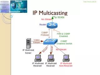
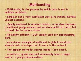
Multicasting • In multicasting communication, there is one source and a group of destinations. The relationship is one-to-many • In this type of communication, the source address is a unicast address, but the destination is a group address, a group of one or more destinations networks in which there is at least one member of the group that is interested in receiving the multicast datagram • The group address defines the members of the group
Note In multicasting, the router may forward the received datagram through several of its interfaces.
Broadcasting • In broadcast communication, the relationship between the source and the destination is one-to-all • There is only one source, but all of the other hosts are the destination • The Internet does not explicitly support broadcasting because of the huge amount of traffic it would create and because of the bandwidth it would need
Multicasting versus Multiple Unicasting • Multicasting starts with one single packet from the source that is duplicated by the routers. The destination address in each packet is the same for all duplicates • In multiple unicasting, several packets start from the source. If there are four destinations, the source sends four packets, each with a different unicast desination address
Emulation of Multicasting with Unicasting • Why we have a separate mechanism for multicasting, when it can be emulated with unicasting • Multicasting is more efficient than multiple unicasting since it requires less bandwidth • In multiple unicasting, the packets are created by the source with a relative delay between packets
Note Emulation of multicasting through multiple unicasting is not efficient and may create long delays, particularly with a large group.
Multicast Applications • Multicasting has many applications today such as • Access to distributed databases • Information dissemination • Dissemination of News • Teleconferencing • Distance learning
12-2 MULTICAST ADDRESSES A multicast address is a destination address for a group of hosts that have joined a multicast group. A packet that uses a multicast address as a destination can reach all members of the group unless there are some filtering restriction by the receiver.
Multicast Addresses in IPv4 • In classful addressing, multicast addresses occupied the only single block in class D • In classless addressing the same block has been used for this purpose • The block assigned for multicasting is 224.0.0.0/4
Local Network Control Block • The addresses in this block are used for protocol control traffic. Some multicast or multicast-related protocols use these addresses • The IP packet with the destination address in this range needs to have the value of TTL set to 1, which means that the routers are not allowed to forward these packets
Internetwork Control Block • The addresses in this block are also used for protocol control traffic, but the IP packets with one of these addresses as destination can be forwarded by router through the whole Internet • For example, the address 224.0.1.1 is used by the NTP protocol
Stream Multicast Group Block • The block 224.1.0.0/16 is called Stream Multicast Group Block and is allocated for stream multimedia
SSM Block • The block 232.0.0.0/8 is used for Source Specific Multicasting. The SSS will later be described in IGMPv3.
GLOP Block • The block 233.0.0.0/8 is called the GLOP block (not an acronym nor an abbreviation) • This block defines a range of globally assigned addresses that can be used inside an autonomous system • Recall that each AS is assigned a 16-bit number. One can insert the AS number as the two middle octet in the block to create a range of 256 multicast addresses (233.x.y.0 to 233.x.y.255), in which x.y is the AS number
Administratively Scoped Block • The block 239.0.0.0/8 is called Administratively Scoped Block • The addresses in this block are used in a particular area of the Internet • The packet whose destination address belongs to this range is not supposed to leave the area. In other words, an address in this block is restricted to an organization
Selecting Multicast Address: Limited Group • The administrator can use the AS number (x.y) and choose an address between 239.x.y.0 and 239.x.y.255 that is not used by any other group • For example, assume a college professor needs to create a group address to communicate with his students. If the AS number that the college belongs to is 91.156 • The college administration can grant the professor, for example, 233.91.156.47. This can become the group address for the professor to use to send multicast addresses to the students • However, the packets cannot go beyond the college AS territory
Selecting Multicast Address: Larger Group • If the group is spread beyond an AS territory, the previous solution does not work • The group needs to choose an address from the SSM block (232.0.0.0/8) • These is no need to get permission to use an address in this block, because the packet in source-specific multicasting are routed based on the group and the source address; they are unique
Delivery of Multicast Packets at Data Link Layer • Most LANs support physical multicast addressing. Ethernet is one of them • An Ethernet physical address is 48 bits long. If the first 25 bits in an Ethernet address are 00000001 00000000 01011110 0, this identifies a physical multicast address for the TCP/IP protocol • The remaining 23 bits can be used to define a group by which the multicast router extracts the lease significant 23 bits of a multicast IP address and inserts them into multicast Ethernet address
Note An Ethernet multicast physical address is in the range 01:00:5E:00:00:00 to 01:00:5E:7F:FF:FF.
Example 12.2 Change the multicast IP address 232.43.14.7 to an Ethernet multicast physical address. Solution We can do this in two steps: a. We write the rightmost 23 bits of the IP address inhexadecimal. This can be done by changing the rightmost 3 bytes to hexadecimal and then subtracting 8 from the leftmost digit if it is greater than or equal to 8. In our example the result is 2B:0E:07. b. We add the result of part a to the starting Ethernet multicast address, which is 01:00:5E:00:00:00. The result is
Example 12.3 Change the multicast IP address 238.212.24.9 to an Ethernet multicast address. Solution We can do this in two steps: a. The rightmost 3 bytes in hexadecimal are D4:18:09. We need to subtract 8 from the leftmost digit, resulting in 54:18:09. b. We add the result of part a to the Ethernet multicast starting address. The result is
Network with No Multicast Support • Most WANs do not support physical multicast address. To send a multicast packet through these networks, a process called tunneling is used • In tunneling, the multicast packet is encapsulated in a unicast packet and sent through the network, where it emerges from the other side as a multicast packet
12-3 IGMP Multicast communication means that a sender sends a message to a group of recipients that are members of the same group. Each multicast router needs to know the list of groups that have at least one loyal member related to each interface. Collection of this type of information is done at two levels: locally and globally. The first task is done by the IGMP protocol; the second task is done by the multicast routing protocols.
Position of IGMP in the network layer • The Internet Group Management Protocol (IGMP) is responsible for correcting and interpreting information about group members in a network • It is one of the protocols designed at the IP layer for this purpose
Group Management • IGMP is not a multicast routing protocol; it is a protocol that manages group membership • The IGMP protocol gives the multicast routers information about the membership status of hosts (routers) connected to the network IGMP is a group management protocol. It helps a multicast router create and update a list of loyal members related to each router interface.
Versions of IGMP • IGMP has gone through 3 versions. Version 1 and 2 provide what is called any-source multicast (ASM), which means that the group members receive a multicast message no matter where it comes from • The IGMP version 3 provides what is called source-specific multicast (SSM), which means that the recipient can choose to receive multicast messages coming from a list of predefined sources
Membership Query Message Format • A membership query message is sent by a router to find active group members in the network.
Membership Query Message Format (cont.) • Maximum Response code. It is used to define the response time of a recipient of the query • Group Address. This field is set to 0 in a general query message; it is set to IP multicast being queried when sending a group-specific or group-and-source specific query message • QRV. This field is called querier’s robustness variable. It is used to monitor robustness in the network • QQIC. This field is called querier’s query interval code. This is used to calculate the querier’s query interval (QQI)
Membership Query Message Format (cont.) • Number of sources (N). This field defines the number of unicast source addresses attached to the query. The value of this field is zero for the general query and the group-specific query, and nonzero in the group-and-source specific query • Source Addresses. These multiple fields list the N source addresses, the origin of multicasat messages
Three formats of query messages • In a general query message, the querier router probes each neighbor to report the whole list of its group membership (interest in any multicast group) • In a group-specific query message, the querier router probes each neighbor to report if it is still interested in a specific multicast group • In a group-and-source-specific query message, the querier router probes each neighbor to report if it is still in a specific multicast group, coming from any of the N sources whose unicast addresses are defined in this packet
Membership Report Message Format (cont.) • Record Type. Currently there are 6 record types
IGMP Protocol Applied to Host: Socket State • The management of groups starts with the processes on a host connected to an interface • Each process, which is associated with a socket, has a record for each multicast group from the socket wishes to receive a multicast message • The record also shows one of the 2 modes: include mode or exclude mode • If the record is in include mode, it lists the unicast source addresses from which the socket accepts the group messages • If the record is in exclude mode, it lists the unicast source address that the socket will not accept the group messages
IGMP Protocol Applied to Host: Socket State (cont.) • In other words, the include mode means “only….,” the exclude mode means “all, but….” • The state can be organized in a table, in which a row defines one single record • A socket may have more than one record if it expects to receive multicast messages destined for more than one group
Example 12.4 Figure 12.11 shows a host with three processes: S1, S2, and S3. The first process has only one record; the second and the third processes each have two records. We have used lowercase alphabet to show the source address.
IGMP Protocol Applied to Host: Interface State • As seen in Figure 12.11, there can be overlap information in the socket records • To be efficient, group management requires that the interface connecting the host to the network also keep an interface state • The interface state will build up when socket records are changed and it keeps only one record for each multicast group • The interface state needs to keep an interface timer for the whole state and one timer for each record • The only problem in combining records is the list of resources. If a record with the same multicast group has 2 or more different lists of resources, the following rules need to be followed to combine the list of resources
IGMP Protocol Applied to Host: Interface State • 1. If any of the records to be combined has the exclusive filter mode, then the resulting interface record will have the exclusive filter mode and the list of the source addresses is made as shown below: • a. Apply the set intersection operation on all the address lists with exclusive filters • b. Apply the set difference operation on the result of part a and all the address lists with inclusive filters
IGMP Protocol Applied to Host: Interface State • 2. If all the records to be combined have the inclusive filter mode, then the resulting interface record will have the inclusive filter mode and the list of the source addresses is found by applying the set union operation on all the address lists Each time there is a change in any socket record, the interface state will change using the above-mentioned rules.
Example 12.5 We use the two rules described above to create the interface state for the host in Example 12.4. First we found the list of source address for each multicast group. a. Multicast group 226.14.5.2 has two exclude lists and one include list. The result is an exclude list as calculated below. b. Multicast group: 228.24.21.4 has two include lists. The result is an include list as calculated below. We use the plus sign for the union operation. Figure 12.12 shows the interface state.