Download

1 / 41
850 likes | 1.93k Views
Fuel System. www.powerpointpresentationon.blogspot.com. Presentation Plan. Fuel oil System Oil burners Coal mills and feeder Types of feeders Classification of Mills Features of different Mills Burner arrangement. Fuel oil System.

E N D
Fuel System www.powerpointpresentationon.blogspot.com
Presentation Plan • Fuel oil System • Oil burners • Coal mills and feeder • Types of feeders • Classification of Mills • Features of different Mills • Burner arrangement
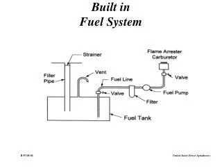
Fuel oil System • Purpose: (a) to establish initial boiler light up. (b) to support the furnace flame during low load operation. • Fuel oil system Consists of • Fuel oil Pumps • Oil heaters • Filters • Steam tracing lines Objective is to get filtered oil at correct pressure and temperature
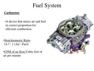
Atomization • Atomization breaks the fuel into fine particles that readily mixes with the air for combustion. Oil should be divided up into small particles for effective atomization. The advantages of atomization are: a) Atomizing burners can be used with heavier grades of oil. b) Can be adopted to large applications because of large capacity range. c) Complete combustion is assured by the ability of the small particles to penetrate turbulent combustion.
Classification: Oil burners Oil burners are classified according to the method used for atomization, as follows: a) Air-atomized burners b) Steam-atomized burners c) Mechanically atomized burners Air atomizing system are not recommended for heavy oil system as they tend to chill the oil and decrease atomization quality
Steam Atomization This System uses auxiliary steam to assist in the atomization of the oil. The steam used in this method should be slightly superheated and free cf moisture. As in the air atomizing system, the steam used for atomizing as well as heating the fuel as it pass through the tip and into the furnace. The main advantages of steam atomizing burners over other are: a) Simplicity of its design b) Initial cost of installation is low c) low pumping pressure d) low preheating temperature. Disadvantage is steam used in atomizing process
Oil Burners The types of oil used in the oil burners are: a) Light Diesel Oil b) Heavyfuel oil c) Low sulpher heavy stock (LSHS). Heavy oil guns are used for stabilizing flame at low load carrying. Warm up oil guns are used for cold boiler warm up during cold start up and ignitor are used for start up and oil flame stabilizing.
Oil Guns The guns used in this system have two main components for atomization. They are: a) Mixing plate b) Spray Plate.
Components The Major components are : • Coal Preparation Equipments • Feeders • Mills • Coal Firing Equipments • Burners
Feeders • Volumetric Type feeder • Chain Feeder • Belt Feeder • Table type belt Feeder • Gravimetric Feeder Chain Feeder
Types of Mills Low Speed Medium Speed High Speed 17 to 20 Rev/min 30 to 100 Rev/min 500 to 1000 Rev/min Tube and ball mill Bowl Mill, Ball and Race mill Beater Mill, Impact Mill Classification-As per Speed
BOWL MILL Model no. Base capacity(T/Hr) 623XRP 18.4 703XRP 26.4 763XRP 33.8 803XRP 36.5 883XRP 51.1 903XRP 54.1 1003XRP 68.1 1043XRP 72.0 BASE CAPACITY(T/HR) AT HGI -55 Total Moisture-10% Fineness-70% THRU 200 MESH
Features of Bowl Mills • Grinding chamber • Classifier mounted above it • Pulverization takes place in rotating bowl • Rolls rotating free on journal do the crushing • Heavy springs provide the pressure between the coal and the rolls • Rolls do not touch the grinding rings • Tramp iron and foreign material discharged.
Pictures of Bowl Mill Coal Entry Classifiers To burners Hot Air Flow from PA Fan Rollers
BALL& RACE MILL(E MILL) Model no. Base capacity(T/Hr) 7E9 25 8.5E10 35 8.5E9 40 10E10 55 10.9E11 61 10.9E10 70 10.9E8 80
TUBE MILL Model no. Base capacity(T/Hr) BBD4760 83 BBD4772 90
Feature of Tube Mill • Operate at 17 to 20 Rpm • Coal Feed from both end of the Tube • Small Ball of 30,40, 50 mm Sizes are used • Hot air blown to move coal to classifiers at two elevations in boiler furnace • No Maintenance for long periods • Better availability so no spare mill required • Always a reserve of coal so there is no spark produced between Steel balls • Consumption of power is more • High Foundation and Initial cost of Equipment
RC Feeder Classifiers 4 No. Drum Feeder Classifiers Distributors 2 No. Hot Air Entry Ball and Tube Mill Coal entry to Drum
Steel Balls Pictures of Tube Mill
Role of Mills • Produces Pulverized coal 80% of which passes through 200 mesh • Air mixed with Pulverized coal (PF) is carried to the coal nozzle in the wind box assembly. • PF from coal nozzle is directed towards the centre of boiler burning zone • Pre-heated secondary air enters boiler and surrounds the PF and help in combustion
Why Pulverized Fuel? The economic motives for the introduction and development of pulverized fuel firing are: i) Efficient utilization of cheaper low grade coals. ii) Flexibility in firing with ability to meet fluctuating loads. iii) Elimination of breaking losses. iv) Better response to automatic control. v) Ability to use high combustion air temperature; increasing the overall efficiency of boiler. vi) High availability.
Mill Dampers and air system • PF temperature to be maintained 900C • All Shut off valves are required to be kept wide open during operation • Mill bearing is to be kept clean and no dust should enter • Low Primary air flow will cause unstable flame and high flow result in high mill reject
Firing System • Direct Firing System:Coal is fed to the mill at controlled quantity. Hot air (temperature controlled) is permitted to flow through the mill. The air dries the coal and picks up the milled product and flows through the classifier rejecting higher size particle. The fine coal is carried through the coal burner to the combustion chamber. • Indirect Firing System:Mills are operated independent of boiler loading and pulverised coal is stored in the intermediate bunker. From the bunker it is taken to combustion chamber with the help of primary air fan. Boiler loading is controlled by the amount of pulverised fuel fed to boiler.
Coal Burners • Coal burners comprise of coal nozzle, steel tip, seal plate and tilting link mechanism. • Housed in coal compartment in all four corners of the furnace and connected with coal pipes. • One end (outlet) is rectangular and another end is cylindrical. • The burner can be tilted on a pivot pin • . The nozzle tip has separate coal and air passages. • Coal and air passages is divided into sevaral parts
Methods of Fuel Firing Vertical Firing :A number of rectangular fan shaped nozzles are set across the width of the furnace in an arch. Pulverised fuel mixture ignites under the arch and is directed vertically downwards to the bottom of the furnace where the gases are made to turn upwards to pass through the combustion chamber this gives a long path to the flame and is particularly suitable for coals oflow volatile content. Horizontal Firing:Horizontal firing with the turbulent type of burner are set up usually in the front (front wall fired) or rear walls of the furnace. Burner consists of an inner cone for primary air and fuel which is given a rotary motion as it passes through the burner. Impact Firing :This is the arrangement with the type of burner used with slag tap furnaces where the ash is kept in a molten state on the furnace floor and tapped off as and when necessary. Corner or tangential Firing:Burners are set at each corner of the furnace and are directed to strike the outside of an imaginary circle in the centre of the furnace.
Various Losses in A Boiler • Heat loss from furnace surface. • Unburned carbon losses. • Incomplete combustion losses. • Loss due to hot ash. • Loss due to moisture in air. • Loss due to moisture in fuel. • Loss due to combustion generated moisture. • Dry Exhaust Gas Losses.