Download
1 / 47
470 likes | 589 Views
Expected Improvements in Imaging. G. Pareschi. INAF – Osservatorio Astronomico di Brera. Outline. Historical remarks on high energy imaging optics Hard X-ray focusing telescope: Simbol-X Wide-field X-ray optics Future large size X-ray missions (XEUS).

E N D
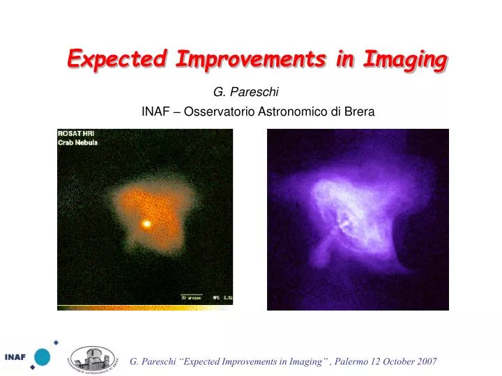
Expected Improvements in Imaging G. Pareschi INAF – Osservatorio Astronomico di Brera
Outline • Historical remarks on high energy imaging optics • Hard X-ray focusing telescope: Simbol-X • Wide-field X-ray optics • Future large size X-ray missions (XEUS)
X-ray astronomical optics history in pills • 1895: Roentgen discovers “X-rays” • 1948:First succesfull attempt of the focalization of an X-ray beam by a total-reflection optics (Baez) • 1952: H. Wolter proposes the use of two-reflection optics based on conics for X-raymicroscopy • 1960: R. Giacconi and B. Rossi propose the use of grazing incidence focusing optics for X-ray telescopes • 1962: discovery by Giacconi et al. of Sco-X1, the first extra-solar X-ray source • 1963: Giacconi and Rossi fly the first (small) Wolter I optics to take images of Sun in X-rays • 1965: second flight of a Wolter I focusing optics (Giacconi + Lindslay) • 1973:SKYLAB carry onboard two small X-ray optics for the study of the Sun • 1978:Einstein, the first satellite with focusing optics enterely dedicated to X-rays • 1983: EXOSAT operated (first European mission with X-ray optics aboard) • 1990:ROSAT, first All Sky Survey in X-rays by means of a focusing telescope with high imaging capabilities • 1993:ASCA, a multimudular focusing telescope with enhanced effective area for spectroscopic purposes • 1996:BeppoSAX, a broad-band satellite with Ni electroformed replicated optics • 1999: launch of Chandra, the X-ray telescope with best angular resolution, and XMM-Newton, the X-ray telescope with most Effective Area • 2004: launch of the Swift satellite devoted to the GRBs investigation (with aboard XRT) • 2005: launch of Suzaku with high throughput optics for enhanced spectroscopy studies with bolometers
Imaging experiments using Bragg reflection from “replicated” mica pseudo-cylindrical optics E. Fermi – Thesis of Laurea, “Formazione di immagini con i raggi Roentgen” (“Imaging formation with Roentgen rays”), Univ. of Pisa (1922) Thanks to Giorgio Palumbo!
Present Astronomical optics technologies: HEW Vs Mass/geometrical area
Present Astronomical optics technologies: HEW Vs Mass/geometrical area
Present Astronomical optics technologies: HEW Vs Mass/geometrical area New Configuration
Cas A ESA credits X-ray optics by Ni electroforming replication BeppoSAX Jet-X/Swift XMM-Newton
Cas A ESA credits X-ray optics by Ni electroforming replication Now the Ni electroforming approach, born and set-up by Citterio et al. For BeppoSAX is a technology almost of-the-shelf for small/medium size missions. It will be used for e-Rosita, SVOM and Polar-X BeppoSAX Jet-X/Swift XMM-Newton
Wolter I geometry The focusing problem in the hard X-ray region (> 10 keV) F = focal length R = reflectivity L = mirror height q = incidence angle
Wolter I geometry Aeff F2 x qc2 x R2 but The focusing problem in the hard X-ray region (> 10 keV) F = focal length R = reflectivity L = mirror height q = incidence angle
Wolter I geometry Aeff F2 x qc2 x R2 but The focusing problem in the hard X-ray region (> 10 keV) At photon energies > 10 keV the cut-off angles for total reflection are very small also for heavy metals the geometrical areas with usual focal lengths (> 10 m) are in general negligible F = focal length R = reflectivity L = mirror height q = incidence angle
Multilayers Focal Length Vs. Diameters for SIMBOL-X and other X-ray telescopes 0.6 o Aeff F2 x qc2 x R2
Multilayers Focal Length Vs. Diameters for SIMBOL-X and other X-ray telescopes 0.6 o The Formation Flight architecture offers the opportunity to implement long FL telescopes! Aeff F2 x qc2 x R2
q Focal length The formation flight contribution
q Focal length The formation flight contribution
q Focal length The formation flight contribution
q Focal length The formation flight contribution
Wide band multilayers X-ray supermirrors Optical supermirrors in a beetle skin b) • Beetle Aspidomorpha Tecta; • TEM section of the skin • b) Reflectivity in the optical band nel visibile. CREDITS: Dr. Naoyuki Ohnishi Chubu University – Japan Dr. Yasushi Ogasaka Nagoya Univ. - Japan a) 1 mm CREDITS: Dr. A. R. Parker – Dep. Of Zoology Oxford University – UK
Simbol-X core scientific objectives • Black hole physics and census • resolve at least 50% of the CXB in the energy range where it peaks (20 -30 keV) • solve the puzzle on the origin of the hard X–ray emission from the Galactic centre • constrain the physics of the accretion flow onto both SMBH and solar mass BH • Particle acceleration mechanisms - constrain acceleration processes in relativistic Jets of blazars and GRB; - probe acceleration mechanisms in the strong EM and gravitational fields of pulsars; - measure the maximum energy of electron acceleration in supernova remnants shocks; These two broad topics define the core scientific objectives ofSimbol-X
Simbol-X core scientific objectives • Black hole physics and census • resolve at least 50% of the CXB in the energy range where it peaks (20 -30 keV) • solve the puzzle on the origin of the hard X–ray emission from the Galactic centre • constrain the physics of the accretion flow onto both SMBH and solar mass BH • Particle acceleration mechanisms - constrain acceleration processes in relativistic Jets of blazars and GRB; - probe acceleration mechanisms in the strong EM and gravitational fields of pulsars; - measure the maximum energy of electron acceleration in supernova remnants shocks; These two broad topics define the core scientific objectives ofSimbol-X
Image quality & large FOV 15” HPD + 12” FWHM High throughput 0.3 – 1 103 cm2 @30keV Low internal background & Rejection of CXB from outside the FOV Wide energy response (0.5 – 80 keV) with high spectroscopic performances Implementation Challenges
C Pt Multilayer coated Ni mirror shells tested at Panter See S. Romaine et al., SPIE Proc., 5900 (2005) • N.B.: a collaboration SAO/NASA-MSFC/INAF-OAB
Low energy detector (450 mm Silicon) High energy detector (2 mm Cd(Zn)Te) Active shielding The Simbol-X focal plane assembly • Spectro-imaging system 0.5-100 keV, fast reading • Full size : 8x8 cm2, 128x128 pixels of 625 mm • Operation at ~ -40°C
Simbol-X Optics • Heritage from XMM–Newton : nickel shells obtained by electroforming replication method; low mass obtained via a reduced thickness of shells • Coating : multi-layer Pt/C needed for requirement on large FOV and on sensitivity up to > 80 keV Focal length : 20 m Shell diameters : 30 to 70 cm Shell thickness : 0.2 to 0.6 mm Number of shells :100 N.B. I: The optics module will have both sides covered with thermal blankets N.B. II: a proton diverter will be implemented
Wide Field Polynomial optics R. Giacconi, “AN EDUCATION IN ASTRONOMY”, Annu. Rev. Astro. Astrophys. 2005.43: 1- 30, 22 “A further extension of this line of thinking is that experiments could be designed by modelling both the hardware and software as part of the initial design. I myself, together with Richard Burg and Chris Burrows, used this approach in designing in the 1980s what I believe was one of the best experiments I ever conceived. The purpose was to scan the sky and to detect distant clusters of galaxies through their X-ray emission. The idea was that it would be possible to equal or exceed the sensitivity of Chandra with an X-ray telescope of one tenth the area (and cost). This could be achieved by dedicating an entire mission of a small satellite to this purpose and by designing a telescope that would have a >16-fold increase of the field of view with respect to Chandra. ……..”
X-ray optics with polynomial profile • Mirrors are usually built in the Wolter I (paraboloid-hyperboloid) configuration which provides, in principle, perfect on-axis images. • This design exhibits no spherical aberration on-axis but suffers from field curvature, coma and astigmatism, which make the angular resolution to degrade rapidly with increasing off-axis angles. • More general mirror designs than Wolter's exist in which the primary and secondary mirror surfaces are expanded as a power series, and the height-to-focal-length ratio optimized • These polynomial solutions are well suited for optimization purposes, which may be used to increase the angular resolution at large off-axis positions, degrading the on-axis performances (Burrows, Burgh and Giacconi 1992) • A trade-off of the whole optics assembly of a wide-field telescope can further on increase the imaging capabilities off-axis of wide-field polynomial optics
WFXT (ASI Phase A study) Tests @ Panter-MPE & Marshall XRF WFXT (epoxy replication on carrier in SiC) Ø = 60 cm Focal Length = 300 cm HEW = 10 arcsec Ref:. O. Citterio, et al., ”, SPIE Proc., 3766, 198 (1999).
EDGE-WFI concept (II) Flux Sensitivity (0.5 – 2 keV): 1.5 10-16 cgs in 1 Msec
Geometric Area and Angular resolution for past and future X-ray telescopes
XEUS (3 x10-18) @ 0.2–8 keV; 4σ Sensitivity (cgs) Effective Area Angular Resolution • 1 (1.5) m2 @ 0.2 keV • 5 m2 @ 1 keV • 2 m2 @ 7 keV • 1 m2 @ 10 keV • (0.1) m2 @ 30 keV 5 (2) arcsec @ < 10 keV 10 arcsec @ 40 keV Field-of-View 7 (10) arcmin diameter: WFI, HXI 1.7 arcmin diameter: NFI
Effective Area (cm2) Area-to-Mass ratio (cm2/kg) HEW (arcsec) 400 0.8 0.5 1400 6.0 15 (12) 50000 35 2 Chandra XMM XEUS XEUS Optics Parameters • Aperture radii 0.67–2.1 m • Grazing reflection angles 0.27–0.86 deg • Focal length 35 m • Plate scale 170μm/arcsec • Total mirror weight ≈ 1.3 tons Optics error Budget Specifications (arcsec) Inherent Intrinsic Extrinsic Environment Total Goal 1.4 1.2 0.5 0.5 2.0 Req. 1.8 3.7 2.0 2.0 5.0
X-ray Pore Optics System Double-Cone approximation N.B.:concept introduced by D. Willingale et al, Capri 1994
Pore Optics technology Credits: ESA & Cosine
Cellular solids: light weight structures with a very high stiffness Foamed Regular cellular structures
Preliminary imaging tests onto two-reflection optics (I) Credits: ESA, Cosine, MPE Collon et al, SPIE Proc 67898, in press (2007)
Preliminary imaging tests onto two-reflection optics (II) Extrapolated HEW for the 4 the first four plates and the entire stack width (~1.2 cm2) of 17 arcsec HEW (BUT JUST IN ONE DIRECTION!) Creditd: Cosine & ESA Extrapolated performance of XOU-3 taking into account beam spreading: At 25 m distance (A) the azimuthal focussing becomes visible and results in a focus at 50 m distance (B). The HEW calculated for the image B (plates 1-4, all 60 pores) is 17” without any corrections Collon et al, SPIE Proc 67898, in press (2007)
Alternative approach: hot sluping of thin glass segments 0.4 mm thick segment (without integration) HEW = 5 arcsec
1: Borofloat sheet and mold Borofloat glass mold 3: Metrology (astatic support) 4: Ion Beam Figuring (if necessary) 2: Slumping Oven Segment production sequence @ INAF-OAB Ghigo et al, 2006
M4 slumping (l/11 on 80 mm) (l/2.9 on 130 mm) Fringes between mould and glass Slumping tests on Borofloat33™ glass sheets The use of a vacuum muffle with the capability to apply on the glass a uniform controlled pressure (~150 g/cm2) provided the best results so far. The muffle protect the glass from the dust of the oven and the vacuum avoid the convection of air slumping (l/11 on 80 mm 50 nm rms) (l/2.9 on 130 mm) No dust specks Circular fringes very sharp up to the edge of the glass 150 mm Zerodur K20 mould