Download
1 / 39
400 likes | 616 Views
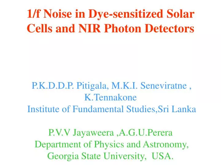
1/f Noise in Dye-sensitized Solar Cells and NIR Photon Detectors P.K.D.D.P. Pitigala, M.K.I. Seneviratne , K.Tennakone Institute of Fundamental Studies,Sri Lanka P.V.V Jayaweera ,A.G.U.Perera Department of Physics and Astronomy, Georgia State University, USA. Dye-sensitized photon detector.

E N D
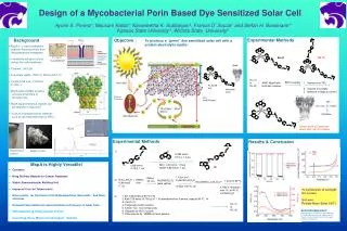
1/f Noise in Dye-sensitized Solar Cells and NIR Photon DetectorsP.K.D.D.P. Pitigala, M.K.I. Seneviratne , K.Tennakone Institute of Fundamental Studies,Sri LankaP.V.V Jayaweera ,A.G.U.Perera Department of Physics and Astronomy, Georgia State University, USA.
Dye-sensitized photon detector Electron collector hn + D→D* D* → D + h+ + e- Hole collector hn S* s
COOH N NSC N Ru II N NSC N HO O OH COOH OH Dye Dye TiO2 Bonding of Dyes to the TiO2 Surface Ru N3 dye Flower Pigment Cyanidin TiO2
CH CH O+ O BF-4 IR-1100 CH CH O O+ BF-4 IR-1135 IR DYES
The problem of thick dye layers Thick dye layers are insulating and also causes quenching, i.e., D* + D* --- → D +D + heat D* + D ---→ D + D + heat Semiconductor Dye Monolayer At monolayer coverage quantum and energy conversion efficiencies are very small because of the poor light absorption by the monolayer.
To increase the photon absorption cross-section dye is deposited on the rough electron conducting surface Hole Collector (Redox electrolyte or p-type semiconductor Dye coverage at monolayer level Light absorption crosssection increased nearly 1000 fold hn Pt TiO2(dyed) Conducting Tin Oxide Glass
Thickness of the light absorbing layer can be made smaller than the exciton or carrier diffusion length L= ( Dt)1/2, while maintaining a large optical absorption cross-section Light absorbing material Electron collector Hole collector Light absorbing material- dye, semiconductor, Q-dots
Efficiencies (E &Q) of dye-sensitized solar cells Cells based on electrolytes ~ E~ 10% , Q ~ 85% Fully solid state cells (solid hole collector) ~ E ~ 4%, Q ~ 60%
Recombination Modes: Dye Sensitized Solar Cells/Photon Detectors 1.Geminate recombination hn + D → D*→ D+ + e- D+ + e-→ D 2. Recombination of the injected electron with an acceptor at dyed oxide surface 3. Recombination of the injected electron with an acceptor at the exposed conducting glass surface.
Injection and Geminate Recombination Rates Injection time D* → D+ + e- , 10-14- 10-15s k = 4p2/h [<i|H|j>]2r(E) ? H = Semicoductor-Dye Electronic Coupling • r(E) = Density of States in the CB • Recombination time D+ + e- → D , 10-5 -10-7s
Recombination of Electrons with Acceptors During Transit Recombination rate =k Recombination Time =k-1= t Mean free path = (Dt)1/2 D+ e-+X→X-
e- e- + X Xֿ + X Xֿ Recombination at the back contact Recombination after leakage from the nano-particle surface
e- Xֿ X Surface trap mediated recombination
Problem of Surface Traps • Surface trap mediated recombination is very severe 2. Trapping and detrapping slows down transport (reduces diffusion coefficient ) 3. Trapping/Detrapping generate noise
a 2R Transition of a trapped electron to a surface state CB E Trapped Electron a = h (2 m * E)-1/2 VB Surface State r When r is comparable to a the probability of transition of the trapped electron to a surface state is high
Recombination of Electrons with Acceptors During Transit Yb Recombinations are generally mediated by surface states D+ e-+X→X- Surface State = Ys Recombination Rate ~ (Ys, Yb) We are not certain whether Yb the wave function of electron in the bulk of the semiconductor is conduction band state or a trapped state
1/f Noise in Mesoscopic Semiconductor films At constant voltage ,current exhibits 1/f ( f=frequency )noise This noise is quite sensitive to trapping-detrapping of carriers
The fluctuating current is of the form I(t) = I0 + X(t) where I0 is the mean and we define S(f) as S(f) gives the noise power spectrum as a function of f
TiO2 Film Conducting Tin Oxide Glass Scribe 56 K 18V Pre-amplifier FT Signal Analyzer A schematic diagram illustrating (a) sample geometry used for the noise measurement. (b) The circuit used for the noise measurement. (a) (b)
S(f) generally satisfy Hoog’s Formula The constant A measures the level of noise and d is an exponent close to unity.
(c) TiO2 (N2, I2) (b) TiO2 (N2 RH=70%) (i) TiO2/N3 (N2, RH=70%) (h) TiO2/BPR (N2, RH=70%) (a) TiO2 (N2) (d) TiO2/BPR (N2) (e) TiO2/N3 (N2) (f) TiO2/BPR (N2, I2) (g) TiO2/N3 (N2, I2) (j) TiO2 (vacuum) (k) TiO2/BPR (vacuum) (l) TiO2/N3 (vacuum) Noise spectra at 23°C of, (a) bare TiO2 film in N2. (b) bare TiO2 film in N2 at RH ~70 %. (c) bare TiO2 in a N2 saturated with I2 vapor. (d) TiO2/BPR in N2. (e) TiO2/N3 in N2. (f) TiO2/BPR in N2 saturated with I2. (g) TiO2/N3 in N2 saturated with I2. (h) TiO2/BPR in N2 at RH ~70 %. (i) TiO2/N3 in N2 at RH ~70%.
The values of parameters A and δ for different systems obtained by fitting noise data to the formulae (1), biasing voltage = 18 V : Io = 3.2×10⁻⁴ A.
Results of the Noise Measurement 1. TiO2film in vacuum or N2 no 1/f noise 2.TiO2 film in N2 with traces of I2 intense 1/f noise • Dyed TiO2 film in N2 with iodine no 1/f noise Electron acceptor states created by adsorbed iodine creates 1/f noise. The dye passivates acceptor states.
When the nanocrystalline surface is bonded with a suitable dye , the trapping sites are passivated. 1/f noise suppressed Recombination suppressed Electron transport facilitated (Ddye>> Dbare )
Recombination in Dye-sensitized Devices Surface traps that generate 1/f noise are also the recombination sites.
Conclusion from Noise Experiments Nanocrystalline oxide films are heavily populated with defects, surface states ,adsorbed species etc, that act as trapping (recombination) sites. Passivation by dye adsorption clears most of these traps. Possible applications – Solar Cells, Photon Detectors.
p-CuSCN Nano-TiO2 Conducting glass Dye Gold Dye-sensitized NIR detector
Response time t ~ L2/D L= Film thickness, D = Diffusion coefficient Detectivity ~ 1011 cm Hz-1/2W-1 (812 nm ) Detectivities of the same order for some dyes absorbing in the region 1000 nm Responsitivities are rather low ~ 10-3 A/W
Strategies for improvement Design dyes to achieve the following • Peak absorption • Fast injection slow geminate recombination • Attach ligands to passivate trapping sites
Conclusion High band-gap mesoscopic semiconductors 1.Insensitive to visible/IR 2. Slow carrier transport 3. Noise 4. Recombination of photogenerated carriers All the above ills can be cured in one stroke by bonding the surface with a suitably designed dye
Cells based on Indoline Dyes Indoline organic dyes give high conversion efficiencies ? Understanding of their properties and mode of interaction with TiO2 likely to give very important clues
H C C H C C O H N CH3 N S C S C N H N S H S S H C COOH C N H H H C COOH H Structural Formula of the Indoline dyes D-149 and D-102 D-149 D-102
The Secret of Indolines? Anchorage via carboxylate ligand facilitate electron injection. It seems that basic nitrogen sites in indoline passivates electron accepting acidic sites on TiO2 . Thus recombination and noise suppressed. Indoline like structures can be made to absorb in the NIR region
Photocurrent Action spectra of SnO2 cells sensitized with (a) D-149 and (b) D-102
I-V Characteristics of SnO2 cells sensitized with (a) D-149(b) D-102 and (c) N719 and Dark I-V Characteristics of SnO2 cells sensitized with (d) D-149(e) D-102 and (f) N719 a b c d e f
I-V Parameters of SnO2 cells sensitized with indoline and Ru-bipyridyl dyes
Indoline vs Ru dyes on SnO2 SnO2 based dye-sensitized cells are more susceptible to recombination than TiO2 cells. With SnO2 indolines give efficiencies higher than that Ru bipyridyl dyes It seems that indoline dyes passivates SnO2 surface more effectively closing the recombination sites
Dye-sensitized NIR Detector Dye Conducting Tin Oxide h Gold Glass TiO2 P-CuSCN 36
Conclusion High band-gap mesoscopic semiconductors 1.Insensitive to visible/IR 2. Slow carrier transport 3. Noise 4. Recombination of photogenerated carriers All the above ills can be cured in one stroke by bonding the surface with a suitably designed dye