Download
1 / 24
240 likes | 244 Views
Exploiting Crosstalk to Speed up On-chip Buses. Chunjie Duan Ericsson Wireless, Boulder Sunil P Khatri University of Colorado, Boulder. Outline. Introduction Classification of Cross-talk types The Story so far.. Eliminating 3C and 4C sequences Eliminating 4C sequences

E N D
Exploiting Crosstalk to Speed up On-chip Buses Chunjie Duan Ericsson Wireless, Boulder Sunil P Khatri University of Colorado, Boulder
Outline • Introduction • Classification of Cross-talk types • The Story so far.. • Eliminating 3C and 4C sequences • Eliminating 4C sequences • Eliminating 2C sequences • Eliminating 1C sequences • Experimental Results • Conclusions
v a a CI CI v CL CL CL a CI CI w a v a CI CI v a a CI CI v a a CI CI v CL CL CL CI CI v v CL CL CL CL CL CL a CL CL CL a CL CL CL a s t Introduction • Deep sub-micron process • Verified cross-talk trends • Accurate 3-D capacitance extraction • Delay variation 2.47:1 (200 mm wires, 10X drivers, 0.1 mm technology)
Cross-talk vs Bus Data Pattern • When λ ~ 0.1μm, r = CI/CL ~ 10 (metal 4) • Effective total capacitance depends on bus data sequence : • Best case: 0 x CI • Worst case: 4 x CI 0·CI 0·CI 2·CI 2·CI Ctotal = 4 ·CI Ctotal = 0 ·CI
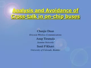
Classification of Cross-talk • 4·C sequence: • 3·C sequence: • 2·C sequence: • 1·C sequence: • 0·C sequence: • Forbidden patterns (“010” and “101”) • Maximum bus data rate depends on total capacitance seen by any bit
Previous work – Eliminating 3C & 4C Sequences • Simple approach: shielding • No 3C/4C sequences ; bus-width is doubled • Theorem: If no forbidden patterns are allowed on the bus, • Proof: see “Analysis and Avoidance of Cross-talk in Buses” – Duan, Tirumala, Khatri (Hot Interconnects August 2001). • So we simply encode the data on the bus to get rid of the forbidden patterns • Recurrence equation for asymptotic bus overhead • CODEC implementation to demonstrate practicality
Eliminating 3C & 4C sequences • 44% asymptotic overhead • Look-Up Table, straightforward, can achieve minimum overhead (44%), but not practical • Our implementation • 62.5% overhead (higher than minimum) • Modular and straightforward • Break bus into 4-bit groups • Encode each group independently (4bit -> 5 bit) • Additional logic to handle across- group forbidden patterns
Previous Work - Eliminating 4C sequences • Less aggressive: eliminating 4C sequences only • Less overhead(33%) • Simpler algorithm: • Divide the bus into 3 bit groups • When 4C sequence occurs, complement group data • Insert group complement indicator • Special handling for across-group 4C sequences (see paper for details) • 101 001 -> 010 010 • 1010 0010 -> 1011 0100
Recovered sequence Recovered sequence Random sequence Random sequence encoder encoder decoder decoder driver driver receiver receiver CODEC Results • Compare waveform with and without coding • Random input sequence • Encoder/decoder delay ~250ps (memoryless) • Max data rate more than 2X compared to scheme with no encoding • Speedup is data pattern independent
CODEC Results … 2 • Bus length 5mm, 10mm or 20mm • Driver strength 30X, 60X and 120X of minimum
Further Speedup Possible? • Can we exploit crosstalk to further speed up the bus? • Eliminate 2C sequences • Eliminate 1C sequences • Simulation shows that eliminating 2C sequences results in a speedup of 2X – 4X over eliminating 3C/4C sequences • Note that we seek memory-less CODEC based techniques • Let’s look at eliminating 2C and 1C sequences next…
Eliminating 2C sequences • How to guarantee a 2C free sequence? • Find a vector clique such that any pair of elements in this clique only exhibit 1C transitions between them • For an n bit bus, we need a k bit encoded bus (k > n) such that the new bus has a 2C free clique of cardinality greater than or equal 2n • Solution is memoryless (no need to “remember” the last transmit word) • Fast and simple CODEC implementation • We have an inductive method to construct 2C free cliques
Constructing 2C free Cliques • Inductive method, extends a known clique Cn = {v} • Let v’ = v . vn • First set Cn+1 = {}, and Cn+1 <= Cn+1 U v’ • Definition: the 0-extended subset of Cn+1 is: • Definition: the 1-extended subset of Cn+1 is: • Constructing • Create a new vector and • Add the vector unless there exist a vector in S1 such that: and • Constructing : similar to • Finally where • Theorem: Both sets of the previous step are 2C free cliques. Proof - see paper
Constructing 2C free Cliques … 2 • Some observations about the construction • Vectors ending with ’01’ and ’10’ can not co-exist in Cn • The first n-bits of any vector of Cn+1 is the same as some vector of Cn and the last two bits are “00” or “11”. • In other words, Cn+1 is at least as large as Cn • Because of (a), we know there will be no “011” or “100” in the same clique Cn+1 • So we can construct vectors of Cn+1 ending in “001” or “110” by add ‘1’ to vectors ending with “00” or add ‘0’ to vectors end with “11”. • However, we can not have both
Constructing 2C free Cliques … 3 • Consider the construction of C4 from C3: • Quadratic number of tests required as described above. We can do better…
Clique Extension Algorithm • Constructing Cn+1 from Cn using the 0-extended subset • Similar algorithm when we use the 1-extended subset • append ‘0’ to n-bit vectors ending with ‘0’ • append ‘1’ to n-bit vectors ending with ‘1’ • since we use the 0-extended subset of Cn+1 • If there is no n-bit vector ending with ’01’ • Append ‘1’ to vectors ending with ’00’ • If there is no n-bit vector ending with ’11’ • Append ‘1’ to vectors ending with ‘10’ • The new clique has no vectors ending with ’10’
Clique Extension Algorithm … 2 • Simply perform both versions of the clique extension algorithm • Select the result according to the rule: • where • Some values of clique sizes:
Area Overhead Trends • Asymptotic overhead is 146% • Lower for smaller bus sizes. • Suggests partitioning of bus into smaller sections
A B C A B C 1C free Configurations • 1C free sequences have least delay (typically 50% of 2C free sequences) • Just send any data bit multiple times (3/5…) • No encoder/decoder needed (no extra codec delay) • Simulation shows it’s the fastest compared to any other techniques with similar area overhead: • 3x (or 5x) separation between wires • Widening the trace (3x): small R, bigger C A B C
Bus configurations for 1C delay • We simulated the delay of several different bus configurations • Different configurations yield different delay and area trade-offs w w w w w variable w w w w w w w w w w variable w w w w w A: 3-wire group, fixed spacing within group, variable spacing between groups. B: similar to A but with a ground shielding between groups. w w w w w w w w w variable w w w w w w w w w variable variable variable D: 5-wire group, fixed spacing within group, variable spacing between groups. largest overhead C: no shielding wires, vary wire sizes and spacing
1C free Configurations • Circuit parameters are extracted using SPACE3D • Bus simulations • CODEC was not modeled • Spice3f5, 0.1μm BPTM model • Transmission line with inter-wire coupling • Quantify actual delay of 1C free bus vector sequences for the 4 configurations described • 20mm wire, 30X driver (IDEAL 1C free delay 153ps, 3C free delay 793ps)
Delays for 1C free Configurations • Configuration C has significantly larger delay than others (3X) since it’s essentially a 3C free configuration (has no shielding) • All other configurations shows up to 2.5X speed up over 3C free bus. • For all configurations, the actually delays are larger than IDEAL 0C delay • This is caused by skew on the outer shielding wires • Transition of dynamic shields of any wire are slightly misaligned • Verified by intentionally skewing the delay on signals
Conclusions • Inter-wire capacitance increasingly significant for DSM VLSI bus delays • We have developed an array of CODECs to trade off bus area overhead with delay • 4C free = 33% • 3C free = 62% • 2C free = 146% (asymptotic), up to 4X to 6X faster • Inductive algorithm for 2C free clique construction • Simulated several 1C free configurations for area overhead and delays (no CODECs) • 1C free techniques not as fast as expected