Download
1 / 44
440 likes | 446 Views
Dr. Brian Mac Namee ( www.comp.dit.ie/bmacnamee ). Mobile Robotics: 3. Actuators. Acknowledgments. These notes are based (heavily) on those provided by the authors to accompany “Introduction to Autonomous Mobile Robots” by Roland Siegwart and Illah R. Nourbakhsh.

E N D
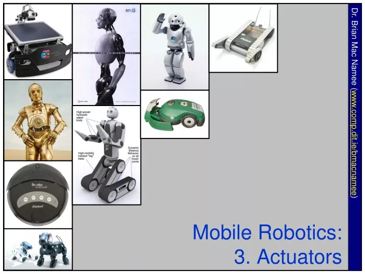
Dr. Brian Mac Namee (www.comp.dit.ie/bmacnamee) Mobile Robotics:3. Actuators
Acknowledgments These notes are based (heavily) on those provided by the authors to accompany “Introduction to Autonomous Mobile Robots” by Roland Siegwart and Illah R. Nourbakhsh More information about the book is available at:http://autonomousmobilerobots.epfl.ch/ The book can be bought at:The MIT Press and Amazon.com
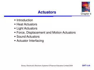
Introduction A robot must be able to interact physically with the environment in which it is operating Actuators are the components of a robot that enable it to affect the environment, say, by exerting forces upon it or moving through it We’ll take a look at: • Electric motors • Artificial muscles • Pneumatics & hydraulics
Robot Joints Robot joints can be either rotary (also known as revolute) or prismatic (telescoping)
Robot Joints (cont…) Prismatic Cartesian robot Rotary SCARA robot
Actuator Control Robots are classified by control method into servo and non-servo robots Non-servo robots are essentially open-loop devices whose movements are limited to predetermined mechanical stops Servo robots use closed-loop computer control to determine their motion
Motor Controller Input Output Open Loop Controller An open-loop controller (or non-feedback controller) is a type of controller which computes its input into a system using only the current state and its model of the system The system does not observe the output of the processes that it is controlling
Open Loop Controller (cont…) Open-loop control is useful for well-defined systems where the relationship between input and the resultant state can be modeled by a mathematical formula For example determining the voltage to be fed to an electric motor that drives a constant load, in order to achieve a desired speed would be a good application of open-loop control
Open Loop Controller (cont…) An open-loop controller is often used in simple processes because of its simplicity and low-cost, especially in systems where feedback is not critical Generally, to obtain a more accurate or more adaptive control, it is necessary to feed the output of the system back to the inputs of the controller
Motor Output Measurement Controller Input Output Feedback Closed Loop Controller A closed-loop controller uses feedback to control states or outputs of a dynamical system Process inputs have an effect on the process outputs, which is measured with sensors and processed by the controller; the result is used as input to the process, closing the loop
Closed Loop Controller Closed-loop controllers have the following advantages over open-loop controllers: • Disturbance rejection (such as unmeasured friction in a motor) • Guaranteed performance even with model uncertainties, when the model structure does not match perfectly the real process and the model parameters are not exact • Unstable processes can be stabilized • Reduced sensitivity to parameter variations • Improved reference tracking performance
Types of Actuators Some of the most common actuators are: • Electric motors, the most common actuators in mobile robots, used both to provide location by powering wheels or legs, and for manipulation by actuating robot arms • Artificial muscles of various types, none of which are very good approximations of living muscles • Pneumatic and hydraulic actuators, used in industry for large manipulation tasks but seldom for mobile robots
Electric Motors Electric motors are the most common source of torque for mobility and/or manipulation in robotics The physical principle of all electric motors is that when an electric current is passed through a conductor (usually a coil of wire) placed within a magnetic field, a force is exerted on the wire causing it to move
Components Of An Electric Motor The principle components of an electric motor are: • North and south magnetic poles to provide a strong magnetic field. Being made of bulky ferrous material they traditionally form the outer casing of the motor and collectively form the stator • An armature, which is a cylindrical ferrous core rotating within the stator and carries a large number of windings made from one or more conductors
Components Of An Electric Motor (cont…) • A commutator, which rotates with the armature and consists of copper contacts attached to the end of the windings • Brushes in fixed positions and in contact with the rotating commutator contacts. They carry direct current to the coils, resulting in the required motion
Stator (Rotating) Commutator Armature Brushes Components Of An Electric Motor (cont…)
How Do Electric Motors Work? The classic DC motor has a rotating armature in the form of an electromagnet A rotary switch called a commutator reverses the direction of the electric current twice every cycle, to flow through the armature so that the poles of the electromagnet push and pull against the permanent magnets on the outside of the motor As the poles of the armature electromagnet pass the poles of the permanent magnets, the commutator reverses the polarity of the armature electromagnet. During that instant of switching polarity, inertia keeps the motor going in the proper direction
How Do Electric Motors Work? (cont…) A simple DC electric motor: when the coil is powered, a magnetic field is generated around the armature. The left side of the armature is pushed away from the left magnet and drawn toward the right, causing rotation
How Do Electric Motors Work? (cont…) The armature continues to rotate
How Do Electric Motors Work? (cont…) When the armature becomes horizontally aligned, the commutator reverses the direction of current through the coil, reversing the magnetic field. The process then repeats.
Electric Motors Electric motors usually have a small rating, ranging up to a few horsepower They are used in small appliances, battery operated vehicles, for medical purposes and in other medical equipment like x-ray machines Electric motors are also used in toys, and in automobiles as auxiliary motors for the purposes of seat adjustment, power windows, sunroof, mirror adjustment, blower motors, engine cooling fans and the like
Stepper Motors When incremental rotary motion is required in a robot, it is possible to use stepper motors A stepper motor possesses the ability to move a specified number of revolutions or fraction of a revolution in order to achieve a fixed and consistent angular movement This is achieved by increasing the numbers of poles on both rotor and stator Additionally, soft magnetic material with many teeth on the rotor and stator cheaply multiplies the number of poles (reluctance motor)
Stepper Motors This figure illustrates the design of a stepper motor, arranged with four magnetic poles arranged around a central rotor Note that the teeth on the rotor have a slightly tighter spacing to those on the stator, this ensures that the two sets of teeth are close to each other but not quite aligned throughout
Stepper Motors (cont…) Movement is achieved when power is applied for short periods to successive magnets Where pairs of teeth are least offset, the electromagnetic pulse causes alignment and a small rotation is achieved, typically 1-2o
How Does A Stepper Motor Work? The top electromagnet (1) is charged, attracting the topmost four teeth of a sprocket.
How Does A Stepper Motor Work? (cont…) The top electromagnet (1) is turned off, and the right electromagnet (2) is charged, pulling the nearest four teeth to the right. This results in a rotation of 3.6°
How Does A Stepper Motor Work? (cont…) The bottom electromagnet (3) is charged; another 3.6° rotation occurs.
How Does A Stepper Motor Work? (cont…) The left electromagnet (4) is enabled, rotating again by 3.6°. When the top electromagnet (1) is again charged, the teeth in the sprocket will have rotated by one tooth position; since there are 25 teeth, it will take 100 steps to make a full rotation.
Stepper Motor Stepper motors have several advantages: • Their control is directly compatible with digital technology • They can be operated open loop by counting steps, with an accuracy of 1 step. • They can be used as holding devices, since they exhibit a high holding torque when the rotor is stationary
Electric Motors: Mounting When used with rotary joint systems, motors can produce torque by being mounted directly on the joints or by pulling on cables The cables can be thought of as tendons that connect the actuator (muscle) to the link being moved Since cables can apply force only when pulled, it is necessary to use a pair of cables to obtain bidirectional motion around a joint, this implies mechanical complexity
Electric Motors: Mounting (cont…) Mounting motors directly on joints allows for bidirectional rotation, but such mounting may increase the physical size and weight of the joint, and this may be undesirable in some applications
Electric Motors: Linear Movement The fact that electric motors produce rotational motion raises an issue with regard to their use in robots For linear translation it is necessary to translate rotational to linear motion • For example, prismatic joints require linear translation rather than rotation from the motor Leadscrews, belt-and-pulley systems, rack-and-pinion systems, or gears and chains are typically used to transform rotational to translational motion
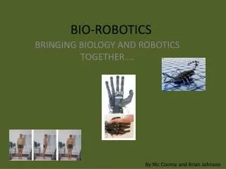
Artificial Muscles During the past forty years a number of attempts have been made to build artificial muscles Muscles contract when activated, since they are attached to bones on two sides of a joint, the longitudinal shortening produces joint rotation Bilateral motion requires pairs of muscles attached on opposite sides of a joint are required to produce
Artificial Muscles: McKibben Type The McKibben muscle was the earliest attempt at constructing an artificial muscle This device consisted of a rubber bladder surrounded by a sleeve made of nylon fibers in a helical weave When activated by pressurized air, the sleeve prevented it from expanding lengthwise, and thus the device shortened like living muscles
Artificial Muscles: McKibben Type In the 1960s there were attempts to use McKibben muscles to produce movements in mechanical structures strapped to nonfunctional arms of quadriplegics The required compresses air was carried in a tank mounted on the person’s wheelchair These experiments were never completely successful
Artificial Muscles: McKibben Type Since the 1960s there has been several other attempts to develop improved McKibben type artificial muscles: • (Brooks, 1977) developed an artificial muscle for control of the arms of the humanoid torso Cog • (Pratt and Williamson 1995) developed artificial muscles for control of leg movements in a biped walking robot However, it is fair to say that no artificial muscles developed to date can match the properties of animal muscles
Artificial Muscles: Shape Memory Alloys Shape memory alloys (SMAs) have unusual mechanical properties Typically, they contract when heated, which is the opposite to what standard metals do when heated (expand) Furthermore, they produce thermal movement (contraction) one hundred times greater than that produced by standard metals
Artificial Muscles: Shape Memory Alloys Because they contract when heated, SMA provide a source of actuation for robots After contraction, the material gradually returns to its original length when the source of activation is removed and it is allowed to cool SMAs have two major problems when used as artificial muscles: • They cannot generate very large forces • They cool slowly and so recover their original length slowly, thus reducing the frequency response of any artificial muscle in which they are employed
Northeastern University’s Robot Lobster A robot lobster developed at Northeastern University used SMAs very cleverly • The force levels required for the lobster’s legs are not excessive for SMAs • Because the robot is used underwater cooling is supplied naturally by seawater More on the robot lobster is available at: http://www.neurotechnology.neu.edu
Artificial Muscles: Electroactive Polymers Like SMAs, Electroactive Polymers (EAPs) also change their shape when electrically stimulated The advantages of EAPs for robotics are that they are able to emulate biological muscles with a high degree of toughness, large actuation strain, and inherent vibration damping Unfortunately, the force actuation and mechanical energy density of EAPs are relatively low
Electroactive Polymer Examples Robotic face developed by a group led by David Hanson. More information is available at: www.hansonrobotics.com Robotic hand developed by a group led by Graham Whiteley. More information is available at: www.elumotion.com
Pneumatic & Hydraulic Actuators Large manipulators in industry frequently employ hydraulic drives, since such drives provide a higher torque-to-weight ratio than electric motors However, because of the maintenance problems associated with pressurized oil (including leaks), hydraulic motors are not used in smaller mobile robots Pneumatic drives have been used as actuators in the past but are not currently popular Air is compressible, resulting in nonlinear behavior of the actuator
Summary Actuators are the components of a robot that interact physically with the environment in which it is operating The key issues with regard to actuators include: • Required power (torque etc) • Power required • Weight etc • Speed