Download
1 / 44
440 likes | 459 Views
Advanced Manufacturing Technology for Weld Operations Applied to Deck Plate and Ship Compartments Presenters : Dr. Stephen Canfield, RTT | Stephen Zuccaro, RTT. March 14, 2019. Charleston, South Carolina. Project Overview. 2017 RA project Collaborative with BIW, EWI, RTT, VT Halter

E N D
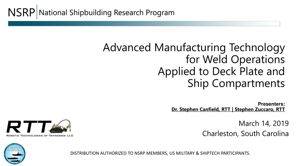
Advanced Manufacturing Technologyfor Weld OperationsApplied to Deck Plate and Ship CompartmentsPresenters:Dr. Stephen Canfield, RTT | Stephen Zuccaro, RTT March 14, 2019 Charleston, South Carolina
Project Overview • 2017 RA project • Collaborative with BIW, EWI, RTT, VT Halter • High-Mobility Manufacturing as evolution of recent robotic advancements • NSRP funded efforts for welding • Collaborative robotics • Man-portable, robotic welding arm to target most common, repetitive weld types • System is termed the HMMR (High Mobility Manufacturing Robot) • Objective is to demonstrate key technical challenges and capabilities
Presentation Overview • Summary of the Project targets and technical approach • Discuss primary component and systems • Present operational approach • Discuss recent developments and testing • Summary and conclusions
WELD TYPE TARGETS Collars Compartments Stiffeners Tie Downs
OVERVIEW OF TECHNICAL REPORTS HMMR – High Mobility Manufacturing Robot Multi-dof mobile manipulator Capable of climbing Man portable Current HMMR exists as a progression of increase mobility machines developed and implemented by RTT:
PROPOSED SOLUTION Maneuverability & Smarts • LiDAR • Sonar • RT Collision detection / safety algorithms • AI Key elements • Mobile Manipulation: Full pose arm on mobile, climbing platform • Operate in multiple orientations (Flat, climb, horiz., vertical) • Real time mapping, localization, obstacle avoidance, task planning
HMMR COMPONENTS: ARM Six DOF (degree of Freedom) Serial Arm Adapted from the AUBO-i5 arm Non-Spherical Wrist
HMMR COMPONENTS: MOBILITY PLATFORM Adaptation of RTT trackless combination • Features include constant pitch drive, distributed adhering forces • Magnetic adhesion • Nominal 400# payload • 0.17 m/s (400 ipm) travel speed • Flat-to-Horizontal-to-vertical transitions • Low profile
HMMR COMPONENTS: ARM MODIFICATIONS Adapting the existing commercial arm to meet ROM and payload requirements for HMMR
HMMR COMPONENTS: PLATFORM MODIFICATION cont.. Adaptations to HMMR 4-wheel drive, 2 drive motors (skid steer) Motor and drive system enclosed in frame chassis structure Wheel positions allow for wall, floor, ceiling transitions (wheels protrude beyond ends of chassis structure) Integrated motor brakes, encoding for precise speed control Front axle articulation Built-in system for removal of platform from climbing surface
SYSTEM DESIGN & INTEGRATION: SENSING Primary scanning LiDAR Data at 10 hz (rotating scans/s) 600 readings/rotation 0.1 mm resolution
SENSING: WORKSPACE MAPPING • Lidar generates scanning planes (continuous) • Lidar scans are integrated with Tool Pose to build Point cloud of workspace • Go from Point cloud to geometry with feature finding alg’s • RANSAC (for example)
PATH / SEAM IDENTIFICATION cont… • Seam detection is extracted from point-cloud data • Local weld-seam variations are observed and adapted in trajectory planning • Also can implement traditional seam review • Develops weld path to execute robot welding motion
SYSTEM DESIGN & INTEGRATION: CONTROL ARCHITECTURE FOR SAFETY • Hardware safety • HMMR incorporates real-time collision detection and avoidance • Adds World map information to collision map in time • Operator safety • 3D mapping scanners operate all the time • Look for dynamic objects in the workspace • Algorithm caps robot speed relative to the presence and location of workers around the workspace
SYS DESIGN & INTEGRATION: WELD TOOL INTEGRATION • Weld tool and sensor package are primary payload • Both located on end-effector frame • Weld tool: Standard machine torch with quick-attach/align fixture • Torch orientation adapted to variety of tasks
SYS DESIGN & INTEGRATION: ELECTRONICS PACKAGING • Power supply and all electronics packaged into mobile base • System input – 110 V AC line • Single cable connection between ARM and BASE
SYS DESIGN & INTEGRATION: OPERATOR INTERFACE Human-Machine Interface (HMI) Industrial tablet with Visual Interface to integrate all robot controls
Automated weld-path teaching • Use Lidar scanning to build a map of the environment • Detect bodies/objects and match to CAD geometry using closest approach algorithms • Identify weld seams based on real-world conditions • Secondary scanning of seams is available
Work flow for weld process Home Screen, Select Weld mode Choose weld seam training mode (autodetect)
Work flow for weld process Initiate Scan, then select desired weld seams Set weld parameters
Work flow for weld process Start the weld Weld parameters can be modified anytime during weld process
SYS DESIGN & INTEGRATION: MAN PORTABLE • ARM ~ 40 lb • BASE ~ 35 lb • Quick deploy system • Preferred operational strategy is the “climb-on” wheel transport • Custom-designed 2-wheel dolly • Robot has automatic “dock” abd “deploy” button to drive onto (or off) dolly. Hands-free on/off docking. • Dolly is easily transported by single user
TASK APPROACH: WELD OPERATOR Step 1: Operator deploys robot at jobsite from transport dolly by selecting job type and starting the scan operation. Step 2: Operator verifies robot determined path and starts weld process. Step 3: After weld, operator moves robot to next job via remotely driving base to near jobs or transport by dolly for farther locations.
TESTING Test results from Edison Welding Institute (EWI), VT Halter Robot Scanning Stiffeners Autonomous Weld of Stiffeners
Testing Evaluation • Downhand and vertical Fillets • Tested using EWI-Developed procedures • Downhand fillets working well, vertical fillets need tuning • Tested ideal and non-ideal fit-ups
Work Flow - Features • Weave Types:
NEXT STEPS & QUESTIONS
PATH / SEAM IDENTIFICATION Point Cloud – built from LiDAR scan of Stiffener Stiffener Mock-up
TECHNICAL CHALLENGES The HMMR (1) finds itself in space, (2) locates the weld and (3) performs the weld 1 2 3
SYS DESIGN & INTEGRATION: KINEMATICS/DYNAMICS Kinematics of AUBO-i5 Schematic of the AUBO-i5 non-spherical wrist
SYS DESIGN & INTEGRATION: ARM KINEMATICS • Notes on Kinematic Solutions to ARM • 8 Solutions in general • Typical 2 solution options for integration with mobile base • ANN used to calculate Inverse Kinematics (10x speed) advantage
SYSTEM DESIGN & INTEGRATION: PLATFORM KINEMATICS/DYNAMICS Equations of Motion: Constraints (forces at IC’s) Dynamics with kinematic coefficients and LM’s exposed:
ANALYTICAL COMPARISON OF SLIP RESULTS • Compare kinematic and dynamic estimates • Kinematic estimates – fixed locations • Dynamic estimates – ICRs form a centrode, L/R traveling in opposite directions • For a specific task, results as reported from the literature
EMPIRICAL VALIDATION OF PLATFORM MODEL • Mobile Robotics Manufacturing Lab • Magnetic-track-based SSMR • 0 .27m track length, 16 magnets per track, 170N adhering force, AT2560 MCU as control node, ROS operating on a Raspberry Pi to define trajectory and gather input motions • Opititrack motion capture system to measure tool-space motion • 18 cameras, 0.5 mm accuracy, 120 hz
INTEGRATED MOBILE MANIPULATOR CONTROL (Arm + Mobile Platform) • Integrated model for Skid-steer mobile robot with torch manipulator • Model includes parameters for slipping Ic Il weld seam θ d1 d2 x y C Ir l b X Y
TASKS Vs. ROBOTS Trapezoidal Profile