Download
1 / 10
230 likes | 843 Views
Multiphase star rectifier. For larger (>15kW) output power. Harmonics and fundamental component. Filter size decreases with the increase of harmonics. Q phase filter has fundamental component of qf frequency. Also known as star rectifier.

E N D
Multiphase star rectifier • For larger (>15kW) output power. • Harmonics and fundamental component. • Filter size decreases with the increase of harmonics. • Q phase filter has fundamental component of qf frequency. • Also known as star rectifier.
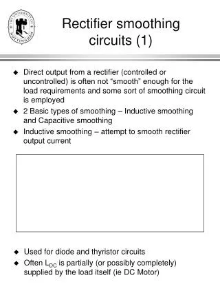
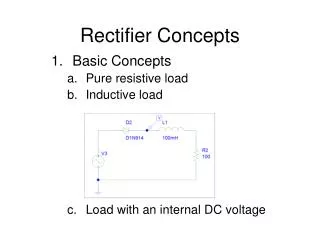
May be considered as q single-phase half-wave rectifier. • K-th diode conducts during the period when the voltage of k-th phase is greater than that of other phases. • The conduction period of each diode is 2π/q. • Primary must be delta connected to compensate the dc component flowing through secondary windings.
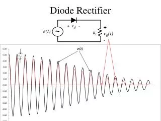
Assuming a cosine wave from π/q to 2π/q, the average o/p voltage is. Output rms voltage is, If the load is purely resistive then peak current through the diode is Im = Vm/R and the rms current through a diode is, (Integrating over the whole period, 2π) Vs is the rms voltage of a transformer secondary
Three phase bridge rectifiers • Full-wave rectifier. • Gives six-pulse ripples on the o/p voltage. • Conduction sequence of diodes are, 12,23,34,45,56,61. • The pair of diodes which are connected between that pair of supply lines having the highest line-to-line instantaneous voltage will conduct. • Line to line voltage,
(Vm is the peak phase voltage) • Average o/p voltage, Rms o/p voltage, For purely resistive load, peak diode current, Rms diode current,
Rms value of transformer secondary current, Where Imis the peak secondary line current = peak diode current,
3-phase bridge rectifier with RL load Where load impedance and load impedance angle The constant A1 can be found from the initial condition: at
Which after substituting in eq (3-82) and then simplifying, gives Rms diode current can be found from above equation as, Rms o/p current is the combination of rms current of each diode.