Download
1 / 94
1.02k likes | 1.5k Views
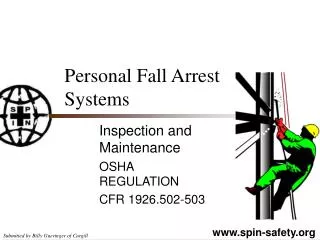
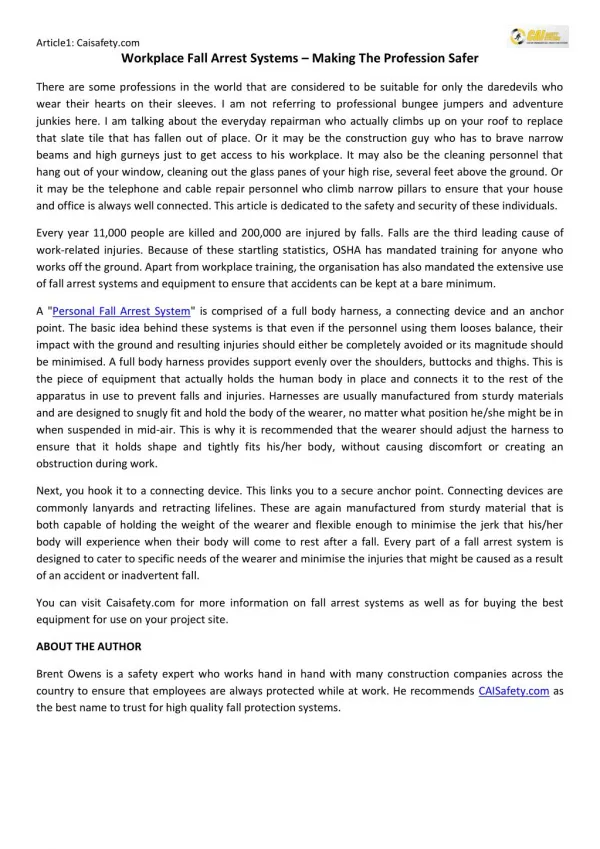
Personal Fall Arrest Systems. “Personal fall arrest system” means a system used to arrest an employee in a fall from a working level. It consists of an anchorage, connectors, a body belt or body harness and may include a lanyard, deceleration device, lifeline, or suitable combinations of these.

E N D
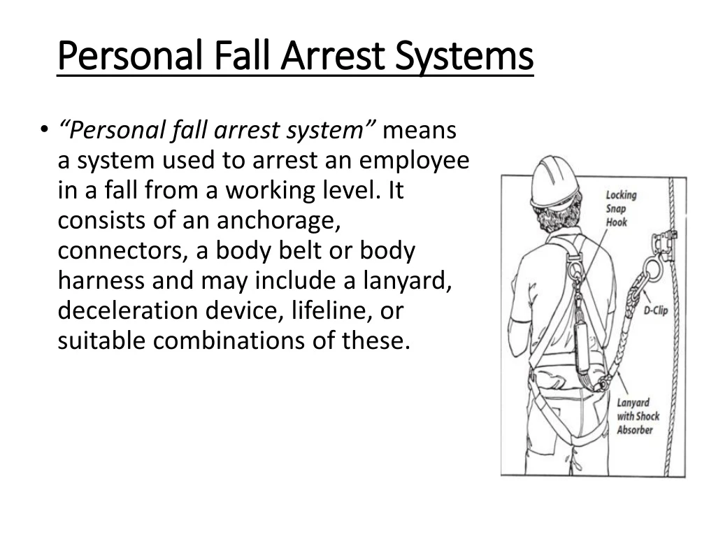
Personal Fall Arrest Systems • “Personal fall arrest system” means a system used to arrest an employee in a fall from a working level. It consists of an anchorage, connectors, a body belt or body harness and may include a lanyard, deceleration device, lifeline, or suitable combinations of these.
Full Body Harness • A full body harness is required for fall arrest. Safety harnesses distribute fall-arrest impact through the thighs and buttocks. Safety belts (waist belts) are no longer permitted for use as personal fall arrest equipment. In a fall arrest, they can cause serious damage to internal organs such as the spleen and pancreas.
Lanyards • Lanyards connect the harness directly to an anchorage such as a rope grab or horizontal static line. • Lanyards should be either rope or synthetic web straps specifically manufactured for such use. • Lanyards should have spliced eyes with thimbles and be fitted with locking snap hooks or D-clips for attachment to other components (Figure 1.16). • Lanyards with shock absorbers are strongly recommended. Never shorten a lanyard by tying knots in it. Knots seriously reduce rope strength. Also, lanyards are not to be looped over an object and then tied back to itself, unless permitted by the manufacturer.
Rope Grabs • Mechanical rope grabs are used to attach lanyards to vertical lifelines. Most rope grabs employ a device that locks on the lifeline when the lanyard is sharply tugged or pulled. Rope grabs must be installed in the right direction. Most grabs are marked with an arrow to indicate correct orientation.
Shock Absorbers Shock absorbers are strongly recommended for use in fall- arrest systems. They are absolutely necessary with wire rope lifelines. Shock absorbers can reduce fall-arrest loads by as much as 50% Some shock absorbers are built into the lanyard. Most are made of webbing material with tear-away stitching designed to gradually absorb a fall-arrest load. The tear-away type also gives clear indication that fall arrest has occurred and that the system should be replaced. This results in better quality control for field equipment. Any fall arrest component involved in a fall arrest should be taken out of service to prevent reuse. It’s done the job it was designed to do!
Anchors • §1926.502(d) Personal Fall Arrest Systems • Anchorages used for attachment of personal fall arrest equipment shall be independent of any anchorage being used to support or suspend platforms and capable of supporting at least 5,000 pounds (22.2 kN) per employee attached, or shall be designed, installed, and used as follows: • as part of a complete personal fall arrest system which maintains a safety factor of at least two; and • under the supervision of a qualified person.
Attaching Anchors • OSHA requires that anchors for PFAS be able to hold at least 5,000 pounds of weight per person, or maintain a safety factor of at least two (twice the impact load) under the supervision of a qualified person. Always follow the anchor manufacturer’s instructions or consult a qualified person when installing anchors to ensure they are strong enough to hold the sudden weight of a falling worker. OSHA believes that anchorages available on the market will meet the strength requirements if they are installed as per the manufacturer’s instructions, with the right number of properly sized nails or screws through the roof sheathing and into one or more roof trusses. Page 32
§1926.502(d) Personal Fall Arrest Systems • Personal fall arrest systems, when stopping a fall, shall: • limit maximum arresting force on an employee to 900 pounds (4 kN) when used with a body belt; • limit maximum arresting force on an employee to 1,800 pounds (8 kN) when used with a body harness; • be rigged such that an employee can neither free fall more than 6 feet (1.8 m), nor contact any lower level; • bring an employee to a complete stop and limit maximum deceleration distance an employee travels to 3.5 feet (1.07 m); and, • have sufficient strength to withstand twice the potential impact energy of an employee free falling a distance of 6 feet (1.8 m), or the free fall distance permitted by the system, whichever is less.
Lifelines • Vertical lifelines must be capable of sustaining a 5000 pound load used by only one worker at a time free of cuts, abrasions, and other defects protected from chafing and abrasion long enough to reach the ground (or a safe landing level above ground) and must be knotted at the bottom to prevent the grab from sliding off the end anchored to a fixed support capable of sustaining a 5000 load.
Horizontal Lifeline: • An engineered horizontal lifeline system, when used as part of a PFAS, is another way to increase the area in which a worker is protected. Install the system following the manufacturer’s instructions and under the supervision of a qualified person. Horizontal lifelines must be designed to maintain a safety factor of at least two (twice the impact load). For requirements for horizontal lifelines, refer to 29 CFR 1926.502(d)(8). Page 30
Lifeline Anchors Page 31
Using Fall Arrest Systems Safely • Ensure that personal fall arrest systems will, when stopping a fall: • Limit maximum arresting force to 1,800 pounds. • Be rigged such that an employee can neither free fall more than 6 feet nor contact any lower level. • Bring an employee to a complete stop and limit maximum deceleration distance to 3½ feet. • Have sufficient strength to withstand twice the potential impact energy of a worker free falling a distance of 6 feet, or the free fall distance permitted by the system, whichever is less • Remove systems and components from service immediately if they have been subjected to fall impact, until inspected by a competent person and deemed undamaged and suitable for use. • Promptly rescue employees in the event of a fall, or assure that they are able to rescue themselves. • Inspect systems before each use for wear, damage, and other deterioration, and remove defective components from service. • Do not attach fall arrest systems to guardrail systems or hoists. • Rig fall arrest systems to allow movement of the worker only as far as the edge of the walking/working surface, when used at hoist areas.
Distance of Fall Page 33
Inspection and Maintenance of Personal Fall Arrest Systems • To maintain their service life and high performance, all belts and harnesses shall be inspected frequently. Visual inspection before each use is required as is a routine inspection by a competent person. If any of the conditions listed below are found the equipment shall be removed from service and replaced before being used. Page 36
Harness Inspection • Belts and Rings: For harness inspections begin at one end, hold the body side of the belt toward you, grasping the belt with your hands six to eight inches apart. Bend the belt in an inverted "U." Watch for frayed edges, broken fibers, pulled stitches, cuts or chemical damage. Check D-rings and D-ring metal wear pads for distortion, cracks, breaks, and rough or sharp edges. The D-ring bar should be at a 90 degree angle with the long axis of the belt and should pivot freely. • Attachments of buckles and D-rings should be given special attention. Note any unusual wear, frayed or cut fibers, or distortion of the buckles. Rivets should be tight and unremovable with fingers. Body side rivet base and outside rivets should be flat against the material. Bent rivets will fail under stress. • Inspect frayed or broken strands. Broken webbing strands generally appear as tufts on the webbing surface. Any broken, cut or burnt stitches will be readily seen. • Tongue Buckle: Buckle tongues should be free of distortion in shape and motion. They should overlap the buckle frame and move freely back and forth in their socket. Rollers should turn freely on the frame. Check for distortion or sharp edges. • Friction Buckle: Inspect the buckle for distortion. The outer bar or center bars must be straight. Pay special attention to corners and attachment points of the center bar. Page 36
Lanyard Inspection • When inspecting lanyards, begin at one end and work to the opposite end. Slowly rotate the lanyard so that the entire circumference is checked. Spliced ends require particular attention. Hardware should be examined under procedures detailed below. • Hardware • Snaps: Inspect closely for hook and eye distortion, cracks, corrosion, or pitted surfaces. The keeper or latch should seat into the nose without binding and should not be distorted or obstructed. The keeper spring should exert sufficient force to firmly close the keeper. Keeper locks must provide the keeper from opening when the keeper closes. • Thimbles: The thimble (protective plastic sleeve) must be firmly seated in the eye of the splice, and the splice should have no loose or cut strands. The edges of the thimble should be free of sharp edges, distortion, or cracks. • Steel Lanyards: While rotating a steel lanyard, watch for cuts, frayed areas, or unusual wear patterns on the wire. The use of steel lanyards for fall protection without a shock-absorbing device is not recommended. Do not use steel lanyards in the presence of electrical hazards. • Web Lanyard: While bending webbing over a piece of pipe, observe each side of the webbed lanyard. This will reveal any cuts or breaks. Due to the limited elasticity of the web lanyard, fall protection without the use of a shock absorber is not recommended. • Rope Lanyard: Rotation of the rope lanyard while inspecting from end to end will bring to light any fuzzy, worn, broken or cut fibers. Weakened areas from extreme loads will appear as a noticeable change in original diameter. The rope diameter should be uniform throughout, following a short break-in period. When a rope lanyard is used for fall protection, a shock-absorbing system should be included. Page 37
Shock-Absorbing Packs Inspection • The outer portion of the shock-absorbing pack should be examined for burn holes and tears. Stitching on areas where the pack is sewn to the D-ring, belt or lanyard should be examined for loose strands, rips and deterioration.
Visual Indication of Damage to Webbing and Rope Lanyards • Heat - In excessive heat, nylon becomes brittle and has a shriveled brownish appearance. Fibers will break when flexed and should not be used above 180 degrees Fahrenheit. • Chemical - Change in color usually appears as a brownish smear or smudge. Transverse cracks appear when belt is bent over tight. This causes a loss of elasticity in the belt. • Ultraviolet Rays - Do not store webbing and rope lanyards in direct sunlight, because ultraviolet rays can reduce the strength of some material. • Molten Metal or Flame - Webbing and rope strands may be fused together by molten metal or flame. Watch for hard, shiny spots or a hard and brittle feel. Webbing will not support combustion, nylon will. • Paint and Solvents - Paint will penetrate and dry, restricting movements of fibers. Drying agents and solvents in some paints will appear as chemical damage. Page 38
Positioning Device Systems • This system holds the worker in place while keeping his/her hands free to work. Whenever the worker leans back, the system is activated. However, the personal positioning system is not specifically designed for fall arrest purposes.The only time a body belt may be used where there may be a fall is when an employee is using a "positioning device." In §1926.500 of the construction standards for fall protection, a "positioning device system" is defined as a body belt or body harness system rigged to allow an employee to be supported on an elevated vertical surface, such as a wall (or a pole), and work with both hands free while leaning. Therefore, in construction work, a positioning device may be used only to protect a worker on a vertical work surface. These devices may permit a fall of up to 2 feet (0.6 m). They may be used in concrete form work, installation of reinforcing steel, and certain telecommunications work. Since construction workers in bucket trucks, scissor lifts and boom-type elevating work platforms are on a horizontal surface, a positioning device may not be used for those workers. Page 39
Restraint Systems A restraint system prevents a worker from being exposed to any fall. If the employee is protected by a restraint system, either a body belt or a harness may be used. When a restraint system is used for fall protection from an aerial lift or a boom-type elevating work platform, the employer must ensure that the lanyard and anchor are arranged so that the employee is not potentially exposed to falling any distance. While fall restraint systems are not mentioned in OSHA’s fall protection rules, OSHA will accept a properly utilized fall restraint system in lieu of a personal fall arrest system when the restraint system is rigged so that the worker cannot get to the fall hazard. In effect, (if properly used) the system tethers a worker in a manner that will not allow a fall of any distance. A fall restraint system is comprised of a body belt or body harness, an anchorage, connectors, and other necessary equipment. Other components typically include a lanyard, and may also include a lifeline and other devices.
Hole Covers • Cover or guard floor holes as soon as they are created during new construction. • For existing structures, survey the site before working and continually audit as work continues. Guard or cover any openings or holes immediately. • Construct all floor hole covers so they will effectively support two times the weight of employees, equipment, and materials that may be imposed on the cover at any one time. • Secure all floor hole covers to prevent accidental displacement by the wind, equipment, or employees. • All covers shall be color coded or they shall be marked with the word “Hole” or “Cover”. Page 42
Walking / Working Surfaces • Each employee on walking/working surfaces shall be protected from tripping in or stepping into or through holes (including skylights) by personal fall arrest systems, covers, or guardrail systems erected around such holes. • Employees are to also be protected from stepping in or tripping over holes where there is no hazard of falling all the way through the hole. In general as long as the opening meets the definition of a hole it must be protected
Protection from Falling Objects • 1926.502(j) as follows: • "Protection from falling objects." Falling object protection shall comply with the following provisions: • -Toeboards, when used as falling object protection, shall be erected along the edge of the overhead walking/working surface for a distance sufficient to protect employees below. • -Toeboards shall be capable of withstanding, without failure, a force of at least 50 pounds (222 N) applied in any downward or outward direction at any point along the toeboard. • -Toeboards shall be a minimum of 3 1/2 inches (9 cm) in vertical height from their top edge to the level of the walking/working surface. They shall have not more than 1/4 inch (0.6 cm) clearance above the walking/working surface. They shall be solid or have openings not over 1 inch (2.5 cm) in greatest dimension. • -Where tools, equipment, or materials are piled higher than the top edge of a toeboard, paneling or screening shall be erected from the walking/working surface or toeboard to the top of a guardrail system's top rail or midrail, for a distance sufficient to protect employees below. • -Guardrail systems, when used as falling object protection, shall have all openings small enough to prevent passage of potential falling objects. • -During the performance of overhand bricklaying and related work: • -No materials or equipment except masonry and mortar shall be stored within 4 feet (1.2 m) of the working edge. • -Excess mortar, broken or scattered masonry units, and all other materials and debris shall be kept clear from the work area by removal at regular intervals. • -During the performance of roofing work: • -Materials and equipment shall not be stored within 6 feet (1.8 m) of a roof edge unless guardrails are erected at the edge. • -Materials which are piled, grouped, or stacked near a roof edge shall be stable and self-supporting. • -Canopies, when used as falling object protection, shall be strong enough to prevent collapse and to prevent penetration by any objects which may fall onto the canopy Page 44
Custody of Fall Protection • Reference: 29 CFR 1926.760(e) • Fall protection provided by the steel erector shall remain in the area where steel erection activity has been completed, to be used by other trades, only if the controlling contractor or its authorized representative: • Has directed the steel erector to leave the fall protection in place; and • Has inspected and accepted control and responsibility of the fall protection prior to authorizing persons other than steel erectors to work in the area.
Page 46 Warning Line Systems • Reference 1926.502(f) • "Warning line systems." Warning line systems [See 1926.501(b)(10)] and their use shall comply with the following provisions: • The warning line shall be erected around all sides of the roof work area. • When mechanical equipment is not being used, the warning line shall be erected not less than 6 feet (1.8 m) from the roof edge. • When mechanical equipment is being used, the warning line shall be erected not less than 6 feet (1.8 m) from the roof edge which is parallel to the direction of mechanical equipment operation, and not less than 10 feet (3.1 m) from the roof edge which is perpendicular to the direction of mechanical equipment operation. • Points of access, materials handling areas, storage areas, and hoisting areas shall be connected to the work area by an access path formed by two warning lines. • When the path to a point of access is not in use, a rope, wire, chain, or other barricade, equivalent in strength and height to the warning line, shall be placed across the path at the point where the path intersects the warning line erected around the work area, or the path shall be offset such that a person cannot walk directly into the work area. • Warning lines shall consist of ropes, wires, or chains, and supporting stanchions erected as follows: • The rope, wire, or chain shall be flagged at not more than 6-foot (1.8 m) intervals with high-visibility material; • The rope, wire, or chain shall be rigged and supported in such a way that its lowest point (including sag) is no less than 34 inches (.9 m) from the walking/working surface and its highest point is no more than 39 inches (1.0 m) from the walking/working surface; • After being erected, with the rope, wire, or chain attached, stanchions shall be capable of resisting, without tipping over, a force of at least 16 pounds (71 N) applied horizontally against the stanchion, 30 inches (.8 m) above the walking/working surface, perpendicular to the warning line, and in the direction of the floor, roof, or platform edge; • The rope, wire, or chain shall have a minimum tensile strength of 500 pounds (2.22 kN), and after being attached to the stanchions, shall be capable of supporting, without breaking, the loads applied to the stanchions as prescribed in paragraph (f)(2)(iii) of this section; and • The line shall be attached at each stanchion in such a way that pulling on one section of the line between stanchions will not result in slack being taken up in adjacent sections before the stanchion tips over. • No employee shall be allowed in the area between a roof edge and a warning line unless the employee is performing roofing work in that area. • Mechanical equipment on roofs shall be used or stored only in areas where employees are protected by a warning line system, guardrail system, or personal fall arrest system.
Safety Monitoring Systems • "Safety monitoring systems." Safety monitoring systems [See 1926.501(b)(10) and 1926.502(k)] and their use shall comply with the following provisions: • The employer shall designate a competent person to monitor the safety of other employees and the employer shall ensure that the safety monitor complies with the following requirements: • The safety monitor shall be competent to recognize fall hazards; • The safety monitor shall warn the employee when it appears that the employee is unaware of a fall hazard or is acting in an unsafe manner; • The safety monitor shall be on the same walking/working surface and within visual sighting distance of the employee being monitored; • The safety monitor shall be close enough to communicate orally with the employee; and • The safety monitor shall not have other responsibilities which could take the monitor's attention from the monitoring function. • Mechanical equipment shall not be used or stored in areas where safety monitoring systems are being used to monitor employees engaged in roofing operations on low-slope roofs. • 1926.502(h)(3) • No employee, other than an employee engaged in roofing work [on low-sloped roofs] or an employee covered by a fall protection plan, shall be allowed in an area where an employee is being protected by a safety monitoring system. • Each employee working in a controlled access zone shall be directed to comply promptly with fall hazard warnings from safety monitors.
Controlled Access Zone • Reference 1926.502(g) • "Controlled access zones." Controlled access zones [See 1926.501(b)(9) and 1926.502(k)] and their use shall conform to the following provisions. • When used to control access to areas where leading edge and other operations are taking place the controlled access zone shall be defined by a control line or by any other means that restricts access. • When control lines are used, they shall be erected not less than 6 feet (1.8 m) nor more than 25 feet (7.7 m) from the unprotected or leading edge, except when erecting precast concrete members. • When erecting precast concrete members, the control line shall be erected not less than 6 feet (1.8 m) nor more than 60 feet (18 m) or half the length of the member being erected, whichever is less, from the leading edge. • The control line shall extend along the entire length of the unprotected or leading edge and shall be approximately parallel to the unprotected or leading edge. • The control line shall be connected on each side to a guardrail system or wall. • When used to control access to areas where overhand bricklaying and related work are taking place: • The controlled access zone shall be defined by a control line erected not less than 10 feet (3.1 m) nor more than 15 feet (4.5 m) from the working edge. • The control line shall extend for a distance sufficient for the controlled access zone to enclose all employees performing overhand bricklaying and related work at the working edge and shall be approximately parallel to the working edge. • Additional control lines shall be erected at each end to enclose the controlled access zone. • Only employees engaged in overhand bricklaying or related work shall be permitted in the controlled access zone. • Control lines shall consist of ropes, wires, tapes, or equivalent materials, and supporting stanchions as follows: • Each line shall be flagged or otherwise clearly marked at not more than 6-foot (1.8 m) intervals with high-visibility material. • Each line shall be rigged and supported in such a way that its lowest point (including sag) is not less than 39 inches (1 m) from the walking/working surface and its highest point is not more than 45 inches (1.3 m) [50 inches (1.3 m) when overhand bricklaying operations are being performed] from the walking/working surface. • Each line shall have a minimum breaking strength of 200 pounds (.88 kN). • On floors and roofs where guardrail systems are not in place prior to the beginning of overhand bricklaying operations, controlled access zones shall be enlarged, as necessary, to enclose all points of access, material handling areas, and storage areas. • On floors and roofs where guardrail systems are in place, but need to be removed to allow overhand bricklaying work or leading edge work to take place, only that portion of the guardrail necessary to accomplish that day's work shall be removed. Page 48
Controlled Decking Zone (CDZ). • Reference Subpart R – Steel Erection, Controlled Decking Zone’s (CDZ) located in 1926.760(c) • 1926.760(c) • A controlled decking zone may be established in that area of the structure over 15 and up to 30 feet above a lower level where metal decking is initially being installed and forms the leading edge of a work area. In each CDZ, the following shall apply: • -Each employee working at the leading edge in a CDZ shall be protected from fall hazards of more than two stories or 30 feet (9.1 m), whichever is less. • -Access to a CDZ shall be limited to only those employees engaged in leading edge work. • -The boundaries of a CDZ shall be designated and clearly marked. The CDZ shall not be more than 90 feet (27.4 m) wide and 90 (27.4 m) feet deep from any leading edge. The CDZ shall be marked by the use of control lines or the equivalent. Examples of acceptable procedures for demarcating CDZ's can be found in Appendix D to this subpart. • -Each employee working in a CDZ shall have completed CDZ training in accordance with § 1926.761. • -Unsecured decking in a CDZ shall not exceed 3,000 square feet (914.4 m 2). • -Safety deck attachments shall be performed in the CDZ from the leading edge back to the control line and shall have at least two attachments for each metal decking panel. • -Final deck attachments and installation of shear connectors shall not be performed in the CDZ. Page 49
Fall Protection Plans • Reference 1926.502(k) • "Fall protection plan." This option is available only to employees engaged in leading edge work, precast concrete erection work, or residential construction work (See 1926.501(b)(2), (b)(12), and (b)(13)) who can demonstrate that it is infeasible or it creates a greater hazard to use conventional fall protection equipment. The fall protection plan must conform to the following provisions. • The fall protection plan shall be prepared by a qualified person and developed specifically for the site where the leading edge work, precast concrete work, or residential construction work is being performed and the plan must be maintained up to date. • Any changes to the fall protection plan shall be approved by a qualified person. • A copy of the fall protection plan with all approved changes shall be maintained at the job site. • The implementation of the fall protection plan shall be under the supervision of a competent person. • The fall protection plan shall document the reasons why the use of conventional fall protection systems (guardrail systems, personal fall arrest systems, or safety nets systems) are infeasible or why their use would create a greater hazard.
Fall Protection Plans • The fall protection plan shall include a written discussion of other measures that will be taken to reduce or eliminate the fall hazard for workers who cannot be provided with protection from the conventional fall protection systems. For example, the employer shall discuss the extent to which scaffolds, ladders, or vehicle mounted work platforms can be used to provide a safer working surface and thereby reduce the hazard of falling. • The fall protection plan shall identify each location where conventional fall protection methods cannot be used. These locations shall then be classified as controlled access zones and the employer must comply with the criteria in paragraph (g) of this section. • Where no other alternative measure has been implemented, the employer shall implement a safety monitoring system in conformance with 1926.502(h). • The fall protection plan must include a statement which provides the name or other method of identification for each employee who is designated to work in controlled access zones. No other employees may enter controlled access zones. • In the event an employee falls, or some other related, serious incident occurs, (e.g., a near miss) the employer shall investigate the circumstances of the fall or other incident to determine if the fall protection plan needs to be changed (e.g. new practices, procedures, or training) and shall implement those changes to prevent similar types of falls or incidents Pages 50 and 51
Walking/Working Surfaces Strength and Integrity • The employer must determine if the walking/working surfaces on which its employees are to work have the strength and structural integrity to support the employees safely. Employees must only be allowed to work on any surface only when it has been determined that it is safe to do so. • Examples of walking/working surfaces which need to be evaluatedRoofs & Roofing Supports • Hole Covers (including Skylights) • Scaffolds & Shoring • Piping Systems • Stairways & Ladders • Formwork & Reinforcing Steel • Ramps, Runways, and other Walkways • Concrete Columns & Structures • Steel & Metal Decking • Sidewalks, Pavements, and other Appurtenant Structures
Housekeeping Wrong Right
Unprotected Sides & Edges • “Unprotected sides and edges” means any side or edge (except at entrances to points of access) of a walking/working surface, e.g., floor, roof, ramp, or runway where there is no wall or guardrail system at least 39 inches (1.0 m) high. • Each employee on a walking/working surface (horizontal and vertical surface) with an unprotected side or edge which is 6 feet (1.8 m) or more above a lower level shall be protected from falling by the use of guardrail systems, safety net systems, or personal fall arrest systems. Page 53
Leading Edges • “Leading edge” means the edge of a floor, roof, or formwork for a floor or other walking/working surface (such as the deck) which changes location as additional floor, roof, decking, or formwork sections are placed, formed, or constructed. A leading edge is considered to be an "unprotected side and edge" during periods when it is not actively and continuously under construction. • 1926.501(b)(2)(i)Each employee who is constructing a leading edge 6 feet (1.8 m) or more above lower levels shall be protected from falling by guardrail systems, safety net systems, or personal fall arrest systems. Exception: When the employer can demonstrate that it is infeasible or creates a greater hazard to use these systems, the employer shall develop and implement a fall protection plan which meets the requirements of paragraph (k) of 1926.502.
Hoist Areas • 1926.501(b)(3)Hoist areas." Each employee in a hoist area shall be protected from falling 6 feet (1.8 m) or more to lower levels by guardrail systems or personal fall arrest systems. If guardrail systems, [or chain, gate, or guardrail] or portions thereof, are removed to facilitate the hoisting operation (e.g., during landing of materials), and an employee must lean through the access opening or out over the edge of the access opening (to receive or guide equipment and materials, for example), that employee shall be protected from fall hazards by a personal fall arrest system.
Formwork & Reinforcing Steel • "Formwork" means the total system of support for freshly placed or partially cured concrete, including the mold or sheeting (form) that is in contact with the concrete as well as all supporting members including shores, reshores, hardware, braces, and related hardware. • "Formwork and reinforcing steel." Each employee on the face of formwork or reinforcing steel shall be protected from falling 6 feet (1.8 m) or more to lower levels by personal fall arrest systems, safety net systems, or positioning device systems.
Ramps, Runways/Walkways • “Ramps” means an inclined walking or working surface that is used to gain access to one point from another. • “Runways/Walkways” means a portion of an elevated platform used only for access and not as a work level. • 1926.451(e)(5)(i) Ramps and walkways 6 feet (1.8 m) or more above lower levels shall have guardrail systems which comply with subpart M of this part -- Fall Protection; • 1926.451(e)(5)(ii) No ramp or walkway shall be inclined more than a slope of one (1) vertical to three (3) horizontal (20 degrees above the horizontal). • 1926.451(e)(5)(iii) If the slope of a ramp or a walkway is steeper than one (1) vertical in eight (8) horizontal, the ramp or walkway shall have cleats not more than fourteen (14) inches (35 cm) apart which are securely fastened to the planks to provide footing. • 1926.501(b)(6) "Ramps, runways, and other walkways." Each employee on ramps, runways, and other walkways shall be protected from falling 6 feet (1.8 m) or more to lower levels by guardrail systems. Page 54
Excavations • “Excavation” means any man-made cut, cavity, trench, or depression in an earth surface, formed by earth removal. • “Trench” (Trench excavation)” means a narrow excavation (in relation to its length) made below the surface of the ground. In general, the depth is greater than the width, but the width of a trench (measured at the bottom) is not greater than 15 feet (4.6 m). If forms or other structures are installed or constructed in an excavation so as to reduce the dimension measured from the forms or structure to the side of the excavation to 15 feet (4.6 m) or less (measured at the bottom of the excavation), the excavation is also considered to be a trench. • Walkways shall be provided where employee or equipment required or permitted to cross over excavations. Guardrails which comply with 29 CFR 1926.502(b) shall be provided where walkways are 6 feet or more above lower levels. • 1926.501(b)(7)(i)Each employee at the edge of an excavation 6 feet (1.8 m) or more in depth shall be protected from falling by guardrail systems, fences, or barricades when the excavations are not readily seen because of plant growth or other visual barrier; 1926.501(b)(7)(ii)Each employee at the edge of a well, pit, shaft, and similar excavation 6 feet (1.8 m) or more in depth shall be protected from falling by guardrail systems, fences, barricades, or covers.
Dangerous Equipment • “Dangerous equipment” means equipment (such as pickling or galvanizing tanks, degreasing units, machinery, electrical equipment, and other units) which, as a result of form or function, may be hazardous to employees who fall onto or into such equipment. • Regardless of height, if a worker can fall into or onto dangerous machines or equipment (such as a vat or acid or a conveyor belt) employers must provide guardrails and toe-boards to prevent workers from falling and getting injured. Page 55
Overhand Bricklaying • “Overhand bricklaying and related work” means the process of laying bricks and masonry units such that the surface of the wall to be jointed is on the opposite side of the wall from the mason, requiring the mason to lean over the wall to complete the work. Related work includes mason tending and electrical installation incorporated into the brick wall during the overhand bricklaying process. • Where a mason performs overhand bricklaying and related work 6 feet above lower levels, the requirements for fall protection systems can be satisfied by the use of guardrail systems, safety net systems, personal fall arrest systems, or by creating a controlled access zone in which only employees engaged in overhand bricklaying or related work, works. However controlled access zones are not permitted where the mason is reaching more than 10 inches below the level of the walking/working surface on which he is working. In that instance conventional fall protection such as a guardrail system, safety net system, or personal fall arrest system is required to be used.
Roofing Work on Low-sloped Roofs • “Roofing work” means the hoisting, storage, application, and removal of roofing materials and equipment, including related insulation, sheet metal, and vapor barrier work, but not including the construction of the roof deck. • “Low-slope roof” means a roof having a slope less than or equal to 4 in 12 (vertical to horizontal). • 29 CFR 1926 (b)(10) Roofing work on Low-slope roofs. Except as otherwise provided in paragraph (b) of this section, each employee engaged in roofing activities on low-slope roofs, with unprotected sides and edges 6 feet (1.8 m) or more above lower levels shall be protected from falling by guardrail systems, safety net systems, personal fall arrest systems, or a combination of warning line system and guardrail system, warning line system and safety net system, or warning line system and personal fall arrest system, or warning line system and safety monitoring system. Or, on roofs 50-feet (15.25 m) or less in width (see appendix A to subpart M of this part), the use of a safety monitoring system alone [i.e. without the warning line system] is permitted.
Steep Roofs • “Steep roof” means a roof having a slope greater than 4 in 12 (vertical to horizontal). • 1926.501(b)(11) "Steep roofs." Each employee on a steep roof with unprotected sides and edges 6 feet (1.8 m) or more above lower levels shall be protected from falling by guardrail systems with toeboards, safety net systems, or personal fall arrest systems.
Precast Concrete Erection • "Precast concrete" means concrete members (such as walls, panels, slabs, columns, and beams) which have been formed, cast, and cured prior to final placement in a structure. • 1926.501(b)(12) "Precast concrete erection." Each employee engaged in the erection of precast concrete members (including, but not limited to the erection of wall panels, columns, beams, and floor and roof "tees") and related operations such as grouting of precast concrete members, who is 6 feet (1.8 m) or more above lower levels shall be protected from falling by guardrail systems, safety net systems, or personal fall arrest systems, unless another provision in paragraph (b) of this section provides for an alternative fall protection measure. Exception: When the employer can demonstrate that it is infeasible or creates a greater hazard to use these systems, the employer shall develop and implement a fall protection plan which meets the requirements of paragraph (k) of 1926.502. • Note: There is a presumption that it is feasible and will not create a greater hazard to implement at least one of the above-listed fall protection systems. Accordingly, the employer has the burden of establishing that it is appropriate to implement a fall protection plan which complies with 1926.502(k) for a particular workplace situation, in lieu of implementing any of those systems. Page 57
Residential Construction • OSHA’s interpretation of residential combines two elements, both of which must be satisfied for a project to fall under the definition of “residential construction”. • The end-use of the structure being built must be as a home, i.e., a dwelling, and; • The structure being built must be constructed using traditional wood frame construction materials and methods. • Traditional wood frame construction materials and methods will be characterized by • Framing materials: Wood (or equivalent cold-formed sheet metal stud) framing, not steel or concrete; wooden floor joists and roof structures. • Exterior wall structure: Wood (or equivalent cold-formed sheet metal stud) framing or masonry brick or block. • Methods: Traditional wood frame construction techniques. • NOTE: The limited use of structural steel in a predominantly wood-frame home, such as a steel I-beam to help support wood framing, does not disqualify a structure from being considered residential construction. • Employees working six (6) feet or more above lower levels must be protected by conventional fall protection methods listed in 1926.501(b)(13) ( i.e., guardrail systems, safety net systems, or personal fall arrest systems ) or alternative fall protection measures allowed by other provisions of 29 CFR 1926.501(b) for particular types of work. • An example of an alternative fall protection measure allowed under 1926.501(b) is the use of warning lines and safety monitoring systems during the performance of roofing work on low-sloped roofs. (4 in 12 pitch or less). (See 1926.501(b)(10)) • OSHA allows the use of an effective fall restraint system in lieu of a personal fall arrest system. To be effective, a fall restraint system must be rigged to prevent a worker from reaching a fall hazard and falling over the edge. A fall restraint system may consist of a full body harness or body belt that is connected to an anchor point at the center of a roof by a lanyard of a length that will not allow a worker to physically reach the edge of the roof. • When the employer can demonstrate that it is infeasible or creates a greater hazard to use required fall protection systems, a qualified person must develop a written site-specific fall protection plan in accordance with 1926.502(k) that, among other things, specifies the alternative fall protection methods that will be used to protect workers from falls. Page 58
Wall Openings • “Wall openings” are where the outside bottom edge of the wall opening is 6 feet (1.8 m) or more above lower levels and the inside bottom edge of the wall opening is less than 39 inches (1.0 m) above the walking/working surface. • 29 CFR 1926 (b)(14) Wall openings. Each employee working on, at, above, or near wall openings (including those with chutes attached) where the outside bottom edge of the wall opening is 6 feet (1.8 m) or more above lower levels and the inside bottom edge of the wall opening is less than 39 inches (1.0 m) above the walking/working surface, shall be protected from falling by the use of a guardrail system, a safety net system, or a personal fall arrest system.