Download

1 / 29
300 likes | 357 Views
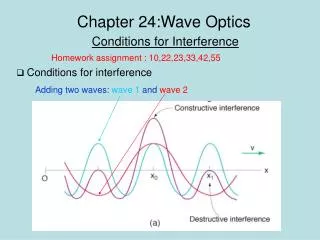
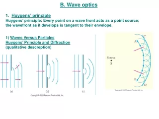
PC20312 Wave Optics. Section 4: Diffraction. Huygens-Fresnel Principle I. Fresnel combined ideas of Huygens’ wavelets & interference Postulated in 1818:.

E N D
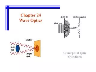
PC20312 Wave Optics Section 4: Diffraction
Huygens-Fresnel Principle I • Fresnel combined ideas of Huygens’ wavelets & interference • Postulated in 1818: “Every unobstructed point of a wavefront… serves as a source of spherical secondary wavelets … The amplitude of the optical field at any point beyond is the superposition of all these wavelets ...” Hecht, p444 Augustin-Jean Fresnel 1788-1827 Image from Wikipedia
Huygens-Fresnel Principle II • Fresnel’s postulate (1818) predates Maxwell’s equations (1861) • Formally derived from the scalar wave equation by Kirchoff in 1882 • Worked with Schuster for year at the University of Heidelberg Gustav R. Kirchhoff 1824-1887 Image from Wikipedia
Huygens-Fresnel Principle III dA3 dA2 P dA1 Optical field at P depends on the superposition of contributions from each elemental area dA of the total area A Total area, A
Huygens-Fresnel Principle IV http://www.acoustics.salford.ac.uk/feschools/waves/diffract3.htm Divide an aperture into elemental areas each of which is a source of a spherical wavelet Image from Wikipedia
The Huygens-Fresnel Integral Q s r Observation point, P Source, S s0 R Spherical wavefront
Fraunhofer diffraction • The case of small, linearphase variation, i.e.: • r R+ r , • r << R • r x,y • Satisfied when s,r >> d • Hence, “Far-field diffraction” y d x aperture Joseph von Fraunhofer 1787-1826 Image from Wikipedia
Far-field diffraction s0 P R d D S • R>>d • const. setK() 1 • D >> d • s0 >> d • wavefront plane at aperture • s s0
Analysis of Fraunhofer diffraction Observation point, P(X,Y) r Q(x,y) R s Source, S s0 Z Aperture, A(x,y)
Single slit diffraction y x -a/2 a/2 Image from Wikipedia
Rectangular aperture y b/2 x -a/2 a/2 -b/2 Image from Wikipedia
y Airy disc u x a Airy rings Circular aperture I The Airy Pattern Image from Wikipedia
Circular aperture II I=0.0175I(0) kaθD=3.83
The diffraction limit • If there was no diffraction: • parallel rays focused to a point • images would be perfectly sharp • BUT, diffraction from instrumental apertures : • produce rays at a range of angles • which are focused at different points • image is thus smeared out. f Even for a perfect optical system, diffraction limits resolution. f Image from Google Images
Radius of the Airy disc Fraunhofer diffraction patterns also formed in focal plane of a lens¶ D f ¶ e.g. see ‘Modern Optics’ by R Guenther Appendix 10-A Radius, RA= fD = 1.22f/d
Two finite slits d x E2(X) a a E1(X) R E1(X)E2(X) X Image courtesy of A Pedlar
Point spread function Images courtesy of A Pedlar & from Wikipedia
The diffraction grating A periodic structure designed to diffract light • Rittenhouse 1785: • fine threads between screws – 100 threads/inch • Fraunhofer 1821: • thin wires • Henry Augustus Rowland: • curved gratings • spectrocopy • Henry Joseph Grayson 1899: • developed precise ‘ruling engine’ • 120,000 lines/inch David Rittenhouse 1732-1796 Henry Augustus Rowland 1848-1901 Images from Wikipedia
Grating structure • Gratings: • central to modern spectrometers • reflection or transmission • amplitude or phase Ruled grating Blazed grating – enhances diffraction in one direction Phase grating
2 1 d Analysis of diffraction from gratings d Path length difference for incident rays: Path length difference for diffracted rays: 2 1 d
Modern gratings Transmission gratings Reflection gratings CDs / DVDs Images from Wikipedia
Gratings in nature Nacre Butterfly wings Peacock feathers Images from Wikipedia
Grating based spectrometers The Czerny-Turner monochromator. • A – input light • B – entrance slit • C – collimating mirror • D – diffraction grating • E – focusing mirror • F – exit slit • G – output light Image from Wikipedia
General diffraction (again) Q s r Observation point, P Source, S s0 R Spherical wavefront
Half-period zones s rm+1 S rm P rm+1 rm P S
Area of the mth zone sd ssind s d ssin ssin S P s rm S P s+R
Merde ! Arago’s spot François Jean Dominique Arago (1783-1856) Siméon Denis Poisson (1781 -1840) http://demo.physics.uiuc.edu/LectDemo/scripts/demo_descript.idc?DemoID=749
Fresnel diffraction from straight edges y Q(x,y) Q(x,y) s r x S P s0 R