Download
1 / 9
90 likes | 198 Views
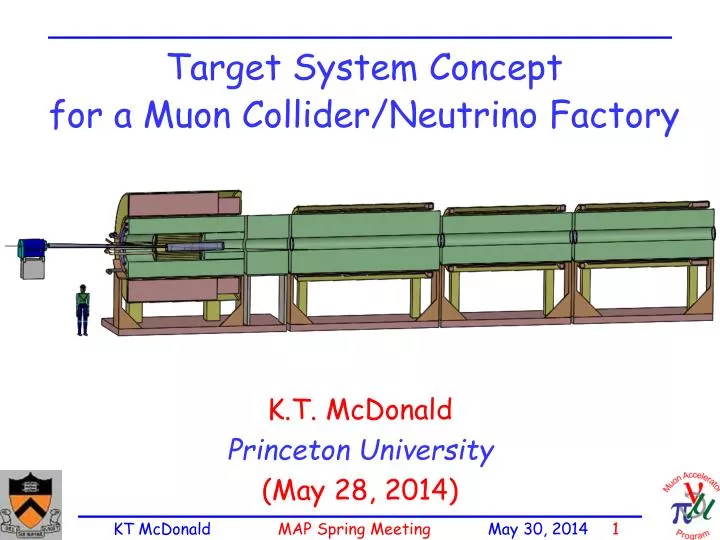
Target System Concept for a Muon Collider/Neutrino Factory. K.T. McDonald Princeton University (May 28, 2014). Specifications from the Muon Accelerator Staging Scenario 6.75 GeV (kinetic energy) proton beam with 3 ns ( rms ) pulse.

E N D
Target System Concept for a Muon Collider/Neutrino Factory K.T. McDonald Princeton University (May 28, 2014)
Specifications from the Muon Accelerator Staging Scenario • 6.75 GeV (kinetic energy) proton beam with 3 ns (rms) pulse. • 1 MW initial beam power, upgradable to 2 MW (perhaps even to 4 MW). • 60 Hz initial rep rate for Neutrino Factory; • 15 Hz rep rate for later Muon Collider. • The goal is to deliver a maximum number of soft muons, • ~ 40 < KE < ~ 180 MeV.
Target System Concept • Graphite target (ρ ~ 1.8 g/cm3), radiation cooled (with option for convection cooling); liquid metal jet as option for 2-4 MW beam power. • Target inside high-field solenoid magnet (20 T) that collects both µ±. • Target and proton beam tilted with respect to magnetic axis. • Superconducting magnet coils shielded by He-gas-cooled W beads. • Proton beam dump via a graphite rod just downstream of the target. • Some of the proton and /µ transport near the target is in air.
Target System Concept 15 T superconducting coil outsert, Stored energy ~ 3 GJ, ~ 100 tons Proton beam tube Last Final-Focus quad Stainless-steel target vessel (double-walled with intramural He-gas flow for cooling) with graphite target and beam dump, and downstream Be window. This vessel would be replaced every few months at 1 MW beam power. Upstream proton beam window 5 T copper-coil insert. Water-cooled, MgO insulated He-gas cooled W-bead shielding (~ 100 tons)
Target System Optimizations • High-Z favored. • Optima for graphite target: length = 80 cm, • radius ~ 8 mm (with σr = 2 mm (rms) beam radius), • tilt angle = 65 mrad, • nominal geometric rms emittance ε = 5 µm. • β* = σr2 /ε = 0.8 m. • Graphite proton beam dump, 120 cm long, 24 mm radius to intercept most of the (diverging) unscattered proton beam. • The 20 T field on target should drop to the ~ 2 T field in the rest of the Front End over ~ 5 m.
Issues for Further Study • Thermal “shock” of the short proton pulse • Probably OK for 2 MW and 60 Hz operation; • 15-Hz option needs study. • Cooling of target, and the W beads. • Lifetime of target against radiation damage. • Beam windows. • * and beam emittance at the target. • To preserve liquid-metal-jet upgrade option, need related infrastructure installed at t = 0.
Thermal Issues for Solid Targets When beam pulse length tis less than target radius r divided by speed of sound vsound, beam-induced pressure waves (thermal shock) are a major issue. Simple model: if U = beam energy deposition in, say, Joules/g, then the instantaneous temperature rise ∆Tis given by ∆T= U /C, where C= heat\ capacity in Joules/g/K. The temperature rise leads to a strain r/rgiven by ∆r/r = α∆T= αU/C, where α= thermal expansion coefficient. The strain leads to a stress P (= force/area) given by P= E∆r/r = EαU/C, where E = modulus of elasticity. In many metals, the tensile strength obeys P ≈ 0.002 E, α ≈ 10-5, and C ≈ 0.3 J/g/K, in which case Umax≈ P C/ Eα ≈ 0.002 ∙ 0.3 / 10-5 ≈ 60 J/g. Graphite @ 1400 C: P = 42.4 Mpa, E = 7.2 Gpa, α = 4.8 10-5, C = 1.4 J/g, Umax≈ 1700 J/g. (α ≈ 1 10-5 for carbon-carbon composite) [A nickel target at FNAL has operated with Umax≈ 1500 J/g.] These arguments are from A Short Course on Targetry, KTM, NuFact03 Summer Institute
How Much Beam Power Can a Solid Target Stand? What is the maximum beam power this material can withstand without cracking, for a 6.75-GeV beam at 15 Hz with area 0.1 cm2? Ans: MARS15 indicates that the peak energy deposition in a “pencil” target is essentially just that of dE/dx, 1.5MeV/(g/cm2) for graphite. Now, 1.5 MeV = 2.4 ∙ 10-13J, so 1500 J/g requires a proton beam intensity of (1500 J/g)/(2.4 ∙ 10-13 Jcm2/g) ≈6 ∙ 1015/cm2. Pmax ≈ 15 Hz ∙ 6.75 109eV ∙ (1.6 ∙ 10-19 J/eV) ∙ (6 1015 /cm2) ∙ 0.1 cm2 ≈ 1 ∙ 107 J/s = 10MW. If graphite cracks under singles pulses of > 1500 J/g, then safe up to 10 MW beam power @ 15 Hz.