Download
1 / 19
250 likes | 303 Views
Vibrationdata. Launch Vehicle Pogo, Combustion Instability and Thrust Oscillation By Tom Irvine. Vibrationdata. Introduction. Pogo is a form of self-excited vibration that sometimes occurs during the launch and ascent of space vehicles powered by liquid propellant rocket engines

E N D
Vibrationdata Launch Vehicle Pogo, Combustion Instability and Thrust Oscillation By Tom Irvine
Vibrationdata Introduction • Pogo is a form of self-excited vibration that sometimes occurs during the launch and ascent of space vehicles powered by liquid propellant rocket engines • The phenomenon is due to a coupling between the first longitudinal resonance of the vehicle and the fuel flow to the rocket engines • As the structure responds to perturbations at its longitudinal resonant frequency, the fuel flow to the rocket engine(s) is accelerated and decelerated, causing the engine thrust to oscillate at the same frequency • These thrust oscillations drive the structural resonance, producing a classical closed-loop instability • Dangerous to the vehicle structure, its payloads, and for manned vehicles, to the astronauts • Coupling between other structural modes may also occur
Gemini Program Titan II Pogo Vibrationdata • The Titan II rocket was used for the Gemini spaceflight program, which was carried out in 1965 and 1966 • Two astronauts flew in each Gemini spacecraft • The rocket fuel was a blend of plain hydrazine and unsymmetrical dimethyl hydrazine • The oxidizer was nitrogen tetroxide • This fuel combination is “hypergolic,” which means that the fuels ignite spontaneously when mixed together • Astronaut Michael Collins wrote: The first stage of the Titan II vibrated longitudinally, so that someone riding on it would be bounced up and down as if on a pogo stick. The vibration was at a relatively high frequency, about 11 cycles per second, with an amplitude of plus or minus 5 Gs in the worst case.
Vibrationdata Saturn V • The Saturn V booster was used for the Apollo program, which was carried out from 1968 to 1972 • Astronauts Neil Armstrong and Buzz Aldrin became the first men to set foot on the Moon, during the Apollo 11 mission in July 1969
Vibrationdata Saturn V Pogo • Aldrin described an unmanned test flight of the Saturn V in 1968: • The entire 360-foot stack bounced like a giant Pogo stick. This dangerous “Pogo effect” had been seen with smaller boosters but was completely unexpected in Saturn V. • Aldrin summarized the design modifications made by Wernher von Braun’s engineering team: • They discovered that the “Pogo effect” was due to a resonating harmonic frequency in the F-1 engines that closely matched the twanging of the booster stack. They corrected the problem by “detuning” the engines’ vibration frequencies. • A violent Pogo effect nevertheless occurred during first stage burn in the Apollo 10 mission in 1969 • The three astronauts were unable to read the vibrating instrument panel • And they were slammed back and forth in their seats, even though they had their restraint straps securely fastened
Apollo 13 Vibrationdata • The Apollo 13 vehicle had a severe pogo vibration with the center engine during second stage burn (unrelated to later oxygen tank explosion) • The engine experienced a 34 G vibration at 16 Hz, flexing the thrust frame by 2.6 inches peak-to-peak • This vibration was apparently localized to the engine frame • The engine frame’s natural frequency may have been excited into resonance • The structural vibration coupled with a pressure oscillation, as recorded by the center engine thrust chamber pressure sensor • Also note that the oscillation was accompanied by an unexpected interaction with the cavitation in the turbopumps • Cavitation is the generation of unwanted bubbles • The flight computer shut down the center engine automatically, as the result of a low pressure switch trigger • The outboard engines burned longer, however, compensating for the loss
Vibrationdata Stage 2 Design Modifications • Engineers made a number of design changes to prevent this problem for Apollo 14 • They added a helium gas accumulator in the liquid oxygen (LOX) line of the center engine • The accumulator is also referred to as a suppresser • The accumulator reservoir served to dampen or absorb fluid pressure oscillations, keeping them out of phase with the vibrations of the thrust structure and engines • The accumulator also lowered the first natural frequency of the propellant line, moving it down below the vehicle structural frequencies • The accumulator was actually designed prior to the Apollo 13 mission but was not ready in time for the flight • In addition, the propellant valves on all five second-stage engines were simplified
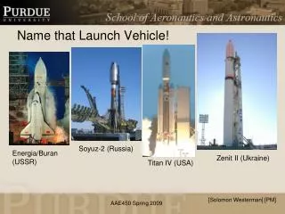
Soviet N-1 Rocket Vibrationdata • The Soviet N-1 rocket had thirty NK-15 rocket engines • Its height was over 100 meters • The N-1 had four unmanned flight tests. Each resulted in failure before first stage separation • The N-1 never had a successful mission • The N-1 had exhaust plume fluid dynamic problems, as well as vibration problems • Pogo vibration was a particular problem for the fourth launch in November 1972 • The pogo occurred at stage 1 initial cutoff in this flight
Vibrationdata Accumulator • A close matching of the propellant and structural frequencies may be prevented by installing an accumulator in the feed line • The accumulator contains a volume of gas that acts like a soft spring to reduce the propellant frequency to well below that of critical structural frequencies • The accumulator volume must be carefully selected to meet this goal
Accumulator Types • Courtesy of the Aerospace Corporation • Some were proposed, others were actually used
Vibrationdata Combustion Instabilities • Combustion in a liquid rocket engine does not occur in an ideal thermodynamic manner • Thermo-acoustic instabilities are characterized by a detrimental coupling between combustion dynamics and the acoustic modes of the combustion chamber • The pressure, temperature, propellant flow rate, and exhaust velocity each experience fluctuations • Propellant pump cavitation and gas entrapment in propellant flow may contribute to these fluctuations • The pressure fluctuation can interact with the natural frequencies of the propellant feed system or the combustion chamber acoustic volume • This interaction causes instability oscillations • A rocket with “smooth combustion” has pressure fluctuations that do not exceed +5% of the mean chamber pressure, during steady operation
Vibrationdata Combustion Instabilities (cont)
Vibrationdata Control of Combustion Instabilities • Reducing the feedback from the combustion process in the main chamber to the fuel injectors can control instability • Three design fixes are: • 1. Modifying the injector design • 2. Increasing the injector pressure drop • 3. Increasing acoustical damping within the combustion chamber • Injector face baffles can be used to minimize coupling and amplification of gas dynamic forces within the chamber • This solution assumes that the driving source of the oscillations is located at the injector end of the combustion chamber
Vibrationdata Helmholtz Resonators • Perforated liners or cavities may be placed along the wall of a combustion chamber • These devices act as Helmholtz resonators that remove oscillation energy from the pressure fluctuations • Reference: G. Sutton, Rocket Propulsion Elements, Fifth Edition, Wiley, New York, 1986 • NASA TN D-3792, D-4968, & D-5171 • Similar technology is used in gas turbine engines and automotive mufflers
Vibrationdata NASA TN D-4968 • Interim Summary of Liquid Rocket Acoustic-Mode-Instability Studies at a Nominal Thrust of 20,000 Pounds • Acoustic liner test configurations • “Several instances have been reported where unstable engines have been made stable by the use of acoustic liners”
Vibrationdata Space Shuttle & Ares I Solid Rocket Boosters • Solid rocket boosters have elongated internal combustion cavities which act as organ pipes • Vortex shedding within the hot exhaust gases drives standing pressure waves inside these cavities • These pressure waves have a fundamental thrust oscillation frequency with integer harmonics • The cavities can be modeled as closed-closed pipes because the nozzle throat diameter is relatively small compared to the cavity diameter • The Space Shuttle boosters’ thrust oscillation frequency was 15 Hz • The Ares I vehicle was projected to have a 12 Hz oscillation (but never flew) • Note that the speed of sound in the internal hot exhaust gas is about 3500 ft/sec Space Shuttle & Ares I Solid Rocket Boosters
Vibrationdata Upper Stage Solid Rocket Motor • Solid rocket motors may have standing pressure oscillations which form in the combustion chamber cavities, caused by vortex-shedding and other effects • This condition is called “Resonant Burn” or “Thrust Oscillation” • The sinusoidal oscillation frequency may sweep downward as the cavity volume increases due to the conversion of propellant to exhaust gas
Flight Accelerometer Data, Resonant Burn, Time History Vibrationdata • Solid Motor Resonance Burn, Accelerometer Data, Full and Close-up Views • The data was collected on a bulkhead in a vehicle with the solid rocket motor on the previous slide
Vibrationdata Flight Accelerometer Data, Resonant Burn, Waterfall FFT • The resonant burn spectral peaks begin at 520 Hz and then sweep downward to 450 Hz • The corresponding amplitude varies with both frequency and time probably due to structural resonance effects as measured by the bulkhead accelerometer • The causes of peaks at 280 and 350 Hz are unknown