Download
1 / 11
110 likes | 201 Views
Target Electronics, DAQ and BPS. MICE/ISIS Target Meeting 17 th September 2010 P J Smith – University of Sheffield. Introduction. Phase 2 Electronics Update Overview and current progress BPS meeting held at RAL on 4 th August 2010 Conclusions

E N D
Target Electronics, DAQ and BPS MICE/ISIS Target Meeting 17th September 2010 P J Smith – University of Sheffield
Introduction Phase 2 Electronics Update • Overview and current progress BPS meeting held at RAL on 4th August 2010 • Conclusions • Presentation of a Firmware Solution through the USBDAQ • Hardware solution? P J Smith - University of Sheffield
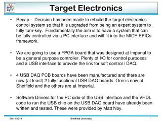
Phase 2 Upgrade The purpose of the Phase 2 upgrade is to integrate the target’s peripheral electronics by moving them from several veroboards to two PCBs that will be fully integrated with the USBDAQ FPGA controller While doing this, the peripheral electronics are being reviewed and where necessary additional functionality is being added. An integrated PSU will be built for the controller Phase 1 involved moving the target’s control algorithms from a PIC based solution to an FPGA so the target electronics could be fully controlled from a GUI. A slow DAQ was also added which provides information on an actuation by actuation basis Phase 1 was ‘completed’ but the FPGA electronics have not been soak tested so they have not yet been installed in ISIS – say more on this later..... Phase 2 may be completed before we need to install the Phase 1 controller. This could be useful as it will allow us to bypass an installation stage P J Smith - University of Sheffield
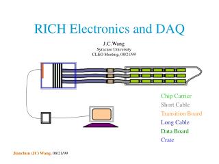
Phase 2 Upgrade Overview of the Phase 1 Upgrade Phase 2 will integrate much of the electronics seen in the crate on the left onto two PCBs Functionality will be improved and an integrated PSU will be added P J Smith - University of Sheffield
Schedule & Progress Phase 2 is scheduled for completion during March 2011 although BPS work may delay this (currently slightly behind schedule due to BPS work) P J Smith - University of Sheffield
BPS We held a meeting at RAL to discuss BPS requirements for the target on the 4th August 2010 It was a very useful meeting as it helped to clarify exactly what was required MICE suggested a hardware solution that involves changing the index marker on the target to give a clear in-beam/not-in-beam signal • This Requires a HW change to the target positioning system • We need to do some analysis of the target motion on capture to ensure that the system isn’t inadvertently triggered • Requires a time window of greater than 20ms (this in principle was not considered a problem) ISIS also requested that we implement a firmware/software system that checks each target actuation to ensure that it falls within acceptable parameters. This check should form part of the BPS P J Smith - University of Sheffield
BPS We feel that adding actuation checking to the FPGA firmware is more robust than implementing a SW solution It is probably just as easy to implement a firmware solution and it would be simplest to logically combine this with any HW generated BPS signal The new target controller automatically generates summary data for each actuation. These data are transmitted to the interface PC and form part of the slow target DAQ data stream. The USB registers (in the FPGA) that hold these data are called: • USB_STATUS_REGISTER • USB_CURRENT_POSITION • USB_ACT_MIN_MAX • USB_ACT_COUNT • USB_ACT_ERROR • USB_ACT_SP • USB_SP1_TIME • USB_MIN_TIME • USB_ACT_TIME • USB_NOTIFY We feel that these FPGA registers will provide the necessary information to determine whether each target actuation is within specification The registers can be checked by the firmware immediately after an actuation, enabling a rapid response to any problems. A FW BPS signal can be generated by the FPGA P J Smith - University of Sheffield
BPS To try and better understand the issues surrounding the BPS we have brought the new Phase 1 controller back from R78 and set it up in our lab at Sheffield. We are just about ready to start running up the rig (hopefully next week) This will enable us to do the following: • Run an older target to collect data about the target’s motion on capture; this will demonstrate whether it is possible to implement a HW BPS signal • It will provide some much needed soak-testing of the Phase 1 controller, something that we have been wanting to do since earlier this year • Once we have ascertained that the actuation by actuation data stream is good, the testing will provide us with several data sets that can be utilised to determine the normal limits of operation over a range of actuation depths • These data sets will then be used to set limits on the FPGA registers in order to define a good actuation (i.e. look up tables). This will form the basis of the FPGA BPS signal P J Smith - University of Sheffield
Schedule for BPS We are working towards having either a FW BPS or a FW + HW BPS signal installed before we start target operations next year The schedule for the BPS is driven by a number of factors: • If we don’t change out the target then we won’t be able to generate a HW BPS signal! • If we wish to generate a HW BPS then the driving factor for this signal is the installation date of the new target • We need additional DAQ data from our lab to ascertain whether a HW BPS is possible without major modification to the target • The Firmware BPS signal must be in place before we start target operations next year. This may involve some additional cabling but the FW signal should not require access to controlled areas. Intend to appoint a RAL liaison – Craig McWaters? P J Smith - University of Sheffield
This schedule was a best ‘guestimate’ of the work involved with the BPS at the start of August Seems reasonable but there are a few lines that need updating
Priorities/ Conclusion The Phase 2 work is progressing well, although the schedule has recently slipped a little as focus has moved to the BPS – this was expected I feel the priority lies with the BPS work because slippage of the Phase 2 schedule has fewer consequences The successful running of the target back in Sheffield will be crucial to taking the BPS work forward. Providing this goes to plan, I think we will have sufficient time to install a FW BPS signal before the target is required next year P J Smith - University of Sheffield