Download
1 / 29
290 likes | 370 Views
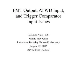
PMT Base Prototypes Comparison using DOMMB ATWD August 6, 2003 Nobuyoshi Kitamura UW-Madison / SSEC. Method Terminal server connected by Python socket program* ATWD chan3 connected to LED pulser current (analog MUX = 2)* CPU trigger on ATWD#0 and capture data* (*Script by Kael Hanson)

E N D
PMT Base Prototypes Comparison using DOMMB ATWD August 6, 2003 Nobuyoshi Kitamura UW-Madison / SSEC
Method Terminal server connected by Python socket program* ATWD chan3 connected to LED pulser current (analog MUX = 2)* CPU trigger on ATWD#0 and capture data* (*Script by Kael Hanson) The rest was also done with a python script (by NK). Background (baseline measurement) with coax connected to dommb but the ribbon cable removed. 100 samples averaged and stored in a file (tagged with a dom ID). (Only 100 samples because of python program speed) Repeatedly captured waveforms (~1Hz), subtracted baseline and displayed on monitor. At random intervals, captured screen (ALT-”print screen”), and pasted to this document. Ten such screen shots are shown here for each configuration. The vertical scale is the ADC counts. 8/6/2003 N. Kitamura
Samples DOMMB only—stand-alone DOMMB in Chamberlin Hall accessed from PSL. The analog input was shunt with a 100Ohm resistor. EMCO—measured with DAC=0 (HV=0) and DAC=2000 (HV=1000V). Old Iseg—single ground configuration. Measured with DAC=0 and without enableHV(), but the on-board oscillator was always on. New Iseg—the split grounds were bridged with a 1MOhm resistor. In addition, the “clean ground” wire was on. The measurement was done under the same conditions as Old Iseg. 8/6/2003 N. Kitamura
Summary / Conclusion (tentative) Fairly large noise is seen in chan0 even with no HV base connected to DOMMB. (Is this a fair measure of the input channel quality?) All the HV base configurations introduce noise to some extent The EMCO base and Old Iseg add somewhat comparable levels of noise to the channels The New Iseg introduces very high levels of nose 8/6/2003 N. Kitamura
DOMMB only 1 8/6/2003 N. Kitamura
DOMMB only 2 8/6/2003 N. Kitamura
DOMMB only 3 8/6/2003 N. Kitamura
DOMMB only 4 8/6/2003 N. Kitamura
DOMMB only 5 8/6/2003 N. Kitamura
EMCO (dac=0) 1 8/6/2003 N. Kitamura
EMCO (dac=0) 2 8/6/2003 N. Kitamura
EMCO (dac=0) 3 8/6/2003 N. Kitamura
EMCO (dac=0) 4 8/6/2003 N. Kitamura
EMCO (dac=0) 5 8/6/2003 N. Kitamura
EMCO (dac=2000) 1 8/6/2003 N. Kitamura
EMCO (dac=2000) 2 8/6/2003 N. Kitamura
EMCO (dac=2000) 3 8/6/2003 N. Kitamura
EMCO (dac=2000) 4 8/6/2003 N. Kitamura
EMCO (dac=2000) 5 8/6/2003 N. Kitamura
Old iseg 1 8/6/2003 N. Kitamura
Old iseg 2 8/6/2003 N. Kitamura
Old iseg 3 8/6/2003 N. Kitamura
Old iseg 4 8/6/2003 N. Kitamura
Old iseg 5 8/6/2003 N. Kitamura
New Iseg 1 8/6/2003 N. Kitamura
New Iseg 2 8/6/2003 N. Kitamura
New Iseg 3 8/6/2003 N. Kitamura
New Iseg 4 8/6/2003 N. Kitamura
New Iseg 5 8/6/2003 N. Kitamura