Download
1 / 33
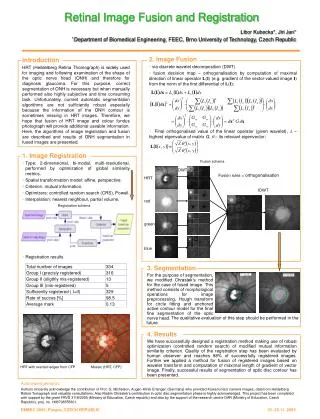
330 likes | 485 Views
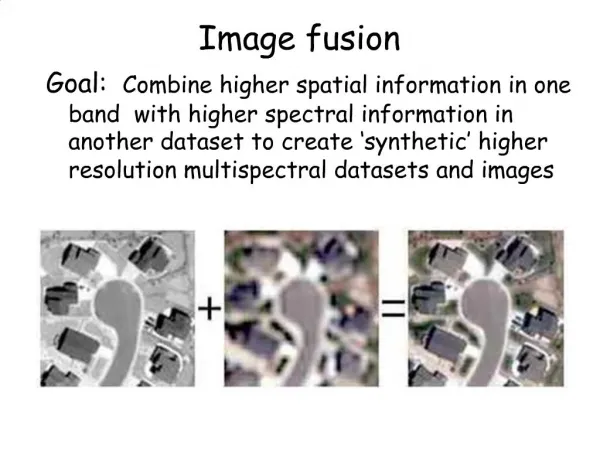
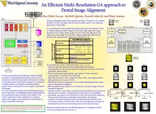
An Efficient Automatic Geo-registration Technique for High Resolution Spaceborne SAR Image Fusion. IGARSS 2011 28/July 2011. Woo-Kyung Lee and A.R. Kim Korea Aerospace University wklee@kau.ac.kr. Motivation. As the resolution level improves,

E N D
An Efficient Automatic Geo-registration Technique for High Resolution Spaceborne SAR Image Fusion IGARSS 2011 28/July 2011 Woo-Kyung Lee and A.R. Kim Korea Aerospace University wklee@kau.ac.kr
Motivation • As the resolution level improves, • * the unique feature of the radar imaging becomes prominent and the task of image fusion with optical image becomes complicated, • * the number of pixels increases and the amount of resources for calculation such as memory and time consumption escalates exponentially. To relieve the burden of the work and make it done in real time. Efficient image matching in both rural and urban regions Simple approach to the SAR image registration and fusion Let the machine do the rest of the job in almost real time One click
SAR SensorandGeometricCharacteristic • Image processing depends on thesurface characteristics and structures • Radar images suffer from unrealistic distortions • Non-linear distortions along range, Shortening from shadow region • Inaccurate Doppler parameter estimation leads to geocoding errors • Unstability in internal system clock and orbit parameters System error Side-looking Observation SAR vs. optics images Image acquisition
SAR SensorandGeometricCharacteristic Error Source Effect of Error SAR sensor - Electronic Time Delay - Slant Range Error - Incidence Angle Estimation - PRF Fluctuation Effect of Error - Range Location - Range Scale - Azimuth Scale Error correction method • - Geometric Calibration • - Deskew • - Ground Projection • - Image Rotation • - Terrain Correction Earth - Azimuth Skew - Range Non-Linearity - Foreshortening, Layover, Shadowing Earth - Earth Rotation - Side-looking - Target Height Source of SAR geocoding errors Platform - Inclination Angle - Yaw Angel Error - Pitch Angle Error Platform - Image Orientation Error - Squint Angle - Doppler Centroid
SAR SensorandGeometricCharacteristic • Mismatch between SAR and Optical images Optics SAR Geometrical distortions in SAR images (a) Azimuth Distortion (b) Non linear Range Error (c) Deskew
SAR Geo-correction with satellite internal data • Slant range function has non linear scale variations Azimuth Slant range image Range Sland based Ground range image Ground projection example Reference image (EO image) Ground Based • Discrepancy exist compared with the reference image • Distortion between SAR and EO are case-sensitive
GCP based geometry registration • A reference image is chosen to be used for geometric correction or fusion • Multiple GCP(Ground Center Point)s are selected and directly applied to individual position error calculation and correction i • Based on the selected GCPs, image transforml function is characterized that best describes the discrepancy between the images • Original image is re-sampled and re-arranged by the generated transform function • To perform geometrical calibration and restore distortion, the GCPs in the SAR images would be re-arranged into the true ground positions • It becomes most essential to pick up the best candidates of GCPs Basic Principle Choice of GCP • In general, distinctive features such as road, building, bridges, reflectors are chosen that are easily discriminated for convenience • Manually? Or Automatically?? Who will chose what points??
Selection of GCPs within SAR images • Speckle noise inherence in SAR image makes it difficult to guarantee to pinpoint precise positions that correspond to the reference points. • A human work of manual GCP selection is never reliable • The number of available points are case-sensitive and still limited by the existence of the distinctive features • The precision of the GCP location is not fully guaranteed and the error variance may increase in coarse resolution images. Difficulty of GCP choice SAR image GCP Optical image GCP
Methodology • Speeded-Up Robust Features (SURF) is known to have highly robust performance • Scale, rotation and illumination-invariant feature descriptor. • Adaptive for noisy environment and mutll-scale images • - Only summing operation is involved in producing integral image to match the scale and calculation is speeded up • Selection of matching points(GCP) are performed using feature vectors described by Hessian Matrix • The size of the constructed Hessian matix can be varied and can be increased to multiple dimensions as desired • The number of dimensions is limited by the complexity, time consumption and precision of the image matching.- case sensitive • Parameters required for the decision algorithms is set intuitively • This work is motivated to find the decision parameters automatically compromising the performance and the complexity SURF algorithm Selection of GCP and matching
Integral image generation • For the given image, an integral set of points are summed together • The size is variable depending on the scale and complexity of the image • Simple summations of intensity levels are performed over two dimensional domain : A +B +C + D
GCP candidate generation • The Hessian matrix , corresponding to each pixel, is simplified by summation with adjacent cells • The image scale is varied and the simplified Hessian matrix is obtained for each scale space • Harr-wavelet responses are calculated and the feature descriptor is generated • The polarity of the image intensity variation is investigated and stored Harr wavelet X, Y direction X direction Y direction
GCP selection • Find a pair of feature descriptors that best fit to each other • One-by-one comparison is straightforward but time-consuming and does not guarantee successful matching due to increased ambiguity • Construct a look-up table for the feature descriptor • Each feature descriptor is indexed depending on their size, variation rate, orientation • For a given GCP , a “search process” is performed within other look-up table generated from reference image and the best matching pair is selected • Nearest neighbor search is adopted to find the correct matching pair Principle
GCP pair selection • - Among the selected GCPs, the Euclidian distance (x, y) – (x’, y’) are estimated to find the nearest points with similar feature descriptor • The rates of intensity variations along orientations (denoted as Aand B) are considered as weighting factors • Distance multiplication is performed • The number of orientation can be increased in order to reduce ambiguity and avoid wrong decision. • Appropriate threshold level is required to compare with the distance multiplication and make a decision • The GCP match is confirmed when the distance multiplication is less than the threshold level • Image Projective Transform function is deduced from the matching GCPs Define threshold level
GCP extraction demonstration • ScanSAR image is exposed to higher noise level and composed of extended resolution cells. • GCP candidates are extracted from both images using the same Hessian matrix structure • The number of GCP points appear to be close to each other despite the gap in the image quality GCP extraction from SAR images (a) Stripmap image (b) Scan image
Geo-registration demonstration • Original SAR image is corrected using GCP matching and transformation • Strip mode SAR image over Vancouver, Canada is geo-registered using the reference image in Radarsat-1 SSG format • The threshold level is set to be zero for convenience 881 557 Time consumption vs Th. Level GCP # vs. Threshold level GCP selection for raw image Raw Reference 912 544 Time consumption vs Th. Level GCP # vs. Threshold level GCP selection for reference image GCP selection
Image Matching Demonstration • Original image is geo-corrected Fusion image
Measure of registration errors • RMSE(Root Mean Square Error) is calculated for the selected GCPs Corrected Reference The average deviation is about one point pixel size
Application to higher resolution images • Reference image of TerraSARin EEC format, Toronto, • The number of GCP increases consistently when the level of correlation between the two images are high As the similarity of the images are high, the GCP increases consistently as the “Threshold Level” decreases 1.72 1595 0.81 252 Original Reference 3.21 2680 GCP variation rate 1.47 404 GCP selection
Image Matching Demonstration After fusion
Mismatch Error Estimate Corrected Reference The average position error is less than one pixel The performance of the matched GCP selection is affected by the image resolution Mismatch error is reduced as the image resolution improves
Image fusion of SAR over EO • This case is where SAR image constitute a small portion of the EO image • GCPs from the two images are distinguished • - The matching GCPs are easily identified by the nearest search algorithm (b) LANDSAT EO image (a) JERS SAR image
Automated threshold level selection There exist a turning point, where further reduction of the threshold level stops affecting the number of GCP matching points Computer traces the variation of the available GCP matches and find the turning point • Threshold variance Threshold 500, Matching image (14 points) Threshold 200, Matching image (15 points) Threshold 350, Matching image (15 points)
GCP matching and Image transformation • Matching GCP selection process stops automatically and image transform function is obtained from the selected points 15 points extraction Feature points extraction Find equation Transform equation
Result of the geo-registration Overlaid image • RMSE is affected by the resolution discrepancy and inherent image property. - Here it is given as 1.26 pixel
Automated Geo-registration software • Usually, the threshold level is manually set-up by user looking into the complexity of the images and resultant fusion performance • This procedure is replaced by compute search algorithm, where the threshold level is traced to find the turning point • Total elapsed time is within several minutes and will be further reduced by adaptive search algorithm Original Reference Corrected GCP selection and matching Fusion
Performance analysis vs. Resolution • The number of total GCP is not affected by modes(Stripmap and Scan) (a) Stripmap image (b) Scan image • However, the RMSE is measured as 0.94 for ScanSAR mode while it is 0.34 for stripmap mode • It appears that the performance improves as the resolution improves
Insufficient information for SAR geometry • Internal data within SAR instrument fails to retrieve shadow region • There is non-linear discrepancy between slant and ground ranges • Generate Errors in geometrical coordinate • Need external references to retrieve broken information and correct errors in ground range allocations • foreshortening, layover, shadowing Limited information Shadowing Layover Foreshortening
Impact of the ground characteristics • Diverse ground geometry becomes a source of matching errors • Mountain areas are severely distorted from the EO case • Need to adopt separate transform functions within the image After correction After correction Coast line area Mountain area Mountain area fusion Coast line fusion
Matching Performance Comparison • Image distortion is not compensated for by the simple GCP transformation • Need to divide blocks and adopt modified transform functions separately Coast line Mountain
Modified Transform functions • Image is divided into blocks according to the geographical properties Average 1.8 RMSE error Mountain Area Average0.67 RMSE Error Urban Area Application of separate transform function leads to the reduction of RMSE
Summary • SURF provides an efficient tool to perform SAR image geo-registration • A choice of threshold level is required to perform efficient of GCP matching and it can be automated by tracing its variation curve • The image matching algorithm works with various SAR and EO images and the average RMSE is measured to be around 1 pixel. • Image blocks containing mountain areas need separate GCP matching and transform function to compensate for image distortion • Need to develop optimized transfer function for different type of ground characteristics • - Indexing of GCP is performed based on their intensity and variation vector • With the introduction of adaptive indexing table for selected GCP, the automated image matching is expected to be carried out in real time Conclusion Further work