Download
1 / 45
450 likes | 513 Views
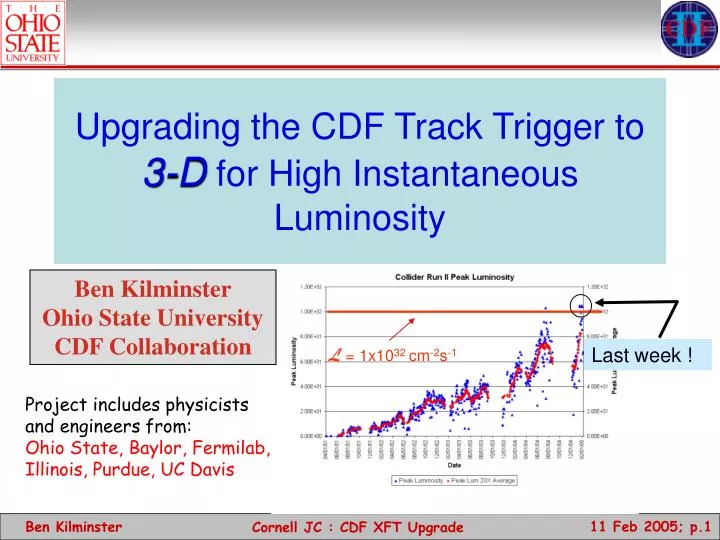
Upgrading the CDF Track Trigger to 3-D for High Instantaneous Luminosity. Ben Kilminster Ohio State University CDF Collaboration. Last week !. L = 1x10 32 cm -2 s -1. Project includes physicists and engineers from: Ohio State, Baylor, Fermilab, Illinois, Purdue, UC Davis.

E N D
Upgrading the CDF Track Trigger to 3-Dfor High Instantaneous Luminosity Ben KilminsterOhio State UniversityCDF Collaboration Last week ! L = 1x1032cm-2s-1 Project includes physicists and engineers from: Ohio State, Baylor, Fermilab, Illinois,Purdue, UC Davis Cornell JC : CDF XFT Upgrade
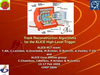
CDF Central Outer Tracker (COT) • 8 “superlayers” of cells • 4 with axial wires: r - f measurement • 4 with stereo wires: z measurement • Each cell • 0.88 cm drift (avg.) • Max drift time ~220 ns • 12 sense wires/cell: 96 measurements • 2540 cells, 30240 channels Cornell JC : CDF XFT Upgrade
eXtremely Fast Tracker = Level 1 Track Trigger CDF Trigger System • Role of tracking • Top, W/Z, ExoticPhysics triggers require High momentum electron and muon Level 1 trigger candidates • Bottom Physics require low momentum tracking at the Level 1 trigger • electrons • muons • hadronic tracks • L1 Trigger Primitives • Electrons: XFT track + EM cluster • Muons: XFT track + muon stub • L2 Trigger Tracks • XFT Track + Silicon Hits Cornell JC : CDF XFT Upgrade
Overview of Existing XFT • Hit Finding: Mezzanine Card • Hits are classified as prompt or delayed (i.e. “2-bin”) • Segment Finding • In the axial layers • patterns of wires within one superlayer • Track Finding • Looking across 3 or 4 axial layers, search for patterns of segments consistent with Pt>1.5 GeV/c Good hit patterns are identified as segment, then segments are linked as tracks Tracks only found in 2-Dimensions (r,f) Cornell JC : CDF XFT Upgrade
The Hit and Segment Finders “Prompt” hit “Delayed” hit Track segments are found by comparing hit patterns in a given layer to a list of valid patterns or “masks”. Hits : 2 bins - Prompt or delayed Mask : A specific pattern of prompt and delayed hits on the 12 wires of an axial COT layer generated by simulating tracks Pixel: represents the phi position of the track at the midpoint of the cell. Cornell JC : CDF XFT Upgrade
Segment Finder Output • In the inner two layers, each mask corresponds to 1 of 12 pixel positions in the middle of the layer. • The pixel represents the phi position of the track. • In the outer 2 layers, each mask corresponds to 1 of 6 pixel positions and 1 of 3 slopes: (low pt +, low pt -, high pt). • When a mask is located, the corresponding pixel is turned on. Cornell JC : CDF XFT Upgrade
The Segment Linker Pixels must match Slopes must match Tracks are found by comparing fired pixels in all 4 layers to a list of valid pixel patterns or “roads”. • Chamber is divided into 288 1.25–degree “identical” Linkers • Highest track reported for each linker • -> Max of 288 tracks per event • Each linker uses a look-up table of ~1200 roads Cornell JC : CDF XFT Upgrade
XFT System Electronics • Mezzanine Cards • 168 cards • Classifies hits as prompt/delayed • Final Finder system • 24 SL1-3 boards • 24 SL2-4 boards • Heavy reliance on PLDs • Allows for some redesign: new patterns for number of misses, wire sag, faster gas, etc • Final Linker System • 24 Linker boards • Heavy reliance on PLDs • Allows for new road set based on new beam positions • Have already developed 2 new roads sets due to accelerator changes. Cornell JC : CDF XFT Upgrade
XFT Performance in CDF RunII • Performance of the XFT in CDF’s RunII has been excellent • Momentum resolution 1.74%/GeV/c • Phi Resolution < 6mRad • Efficiency ~ 95% (almost 100% for high Pt tracks) Cornell JC : CDF XFT Upgrade
Why an Upgrade? • The XFT was designed for a luminosity of: • L=1x1032cm-2s-1 with 396 nsec bunch crossings • <int/crossing> ~ 3 • Then it was supposed to switch to : • L=2x1032cm-2s-1 132nsec bunch • <int/crossing> ~ 2 • But 132ns was not feasible • Accelerator Performance • Max luminosity attained: 1x1032cm-2s-1 • Expect to reach L=3x1032cm-2s-1 at 396nsec bunch crossing • <int/crossing> ~ 9 • Factor of 3-4 above design Design @ 396 ns Design @ 132 ns Cornell JC : CDF XFT Upgrade
Z ee at low lum.0 add. Int./crossing Cornell JC : CDF XFT Upgrade
Z ee at low lum.2 add. Int./crossing Cornell JC : CDF XFT Upgrade
Z ee at low lum.5 add. Int./crossing Cornell JC : CDF XFT Upgrade
Z ee at low lum.10 add. Int./crossing Cornell JC : CDF XFT Upgrade
Z ee at low lum.10 add. Int./crossing Resolution of COT much better than resolution of picture Cornell JC : CDF XFT Upgrade
Two-Track Triggers • Two Track Trigger for B Physics • 2 tracks pT>2.5 GeV • Opposite charge • pT(1)+ pT(2)>6.5 GeV • df < 135 Quadratic growth (overlaps + fakes) • s(L=5E31)/s(L =0)=1.5 • Extrapolate: • linear s(L=1.5E32) = 225mb 34kHz • Real (from overlapped MB) s(L=1.5E32) = 500mb 75kHz Run II Data 160mb 100mb We are stuck with FIXED Bandwidth (Accept Rate): L1: 30 kHz L2: 1 kHz L3: 100 Hz Cornell JC : CDF XFT Upgrade
What’s needed: • Primary problem is the growth of fake tracks due to pattern recognition problems: • Need a way to model the highest luminosity running • Simulations of the XFT System • Study the effect of high luminosity running on a variety of triggers • Two-Track Trigger (low PT) • Single Track Trigger (high PT: Track Only) • Electron Trigger (Track + Other object) • Consider modifications/additions to the current system • Reduce fake rate • Maintain resolution fake Fake tracks can be made from pieces of different real physical tracks. Trigger Rate is the “Figure of Merit” Cornell JC : CDF XFT Upgrade
XFT Simulation of High Lum. • All events are passed through a hit-level simulation • Start with COT hits • Gives exactly the same answer as hardware when run with same masks, roads and XFT hits • Outputs XFT hits, pixels, and tracks for axial and XFT pixels for stereo • Simulate High luminosity by Merging events “main” event with zero bias • Merge COT hits (combine overlapping hits) • simulate XFT with various options • Add tracks from individual events together • Offline tracks serve as “truth” for the event • This method allows us to probe up to 4E32 Cornell JC : CDF XFT Upgrade
Upgrade Strategy Current XFT uses 4 axial layers only • Studied various upgrade paths • Replacing Axial System (Use additional 264ns between crossings) • Add information from Stereo Layers of COT • Replace linker with finer segment linking • Doing some of the above • Advantages of Stereo Upgrade • Gives us the fake track rejection we need. • Allows for more additional handles in trigger • Track pointing to muon stubs & calor (L2) • Possibility of Two-Track Invariant Mass Cuts (Understudy) • Parallel Path to Axial System • Commission parasitically. • Only Minor changes to Axial System • Slight Changes to existing firmware. • KEEP A WORKING SYSTEM • No extended downtime We picked this. Stereo layers Upgrade adds 3 stereo layers. Use full 396ns between crossings to send more precise hit information. Cornell JC : CDF XFT Upgrade
Impact of Stereo • The stereo can have an impact in two ways: • Confirmation Segment: Since often fake XFT tracks are the result of linking two unrelated low Pt segments, requiring another high Pt stereo segment in the allowed window around an axial track can be very powerful. • We will use this at Level 1 • Provide Z-pointing to tracks: Since EM and muon calorimeters are segmented in Z, coarse pointing can be very helpful in eliminating fakes • We can use this effectively at Level 2 one stereo layer rejection Cornell JC : CDF XFT Upgrade
SL7 SL6 SL5 SL3 SL4 Expected pixel position (z = 0) Measured pixel position (z 0) Reals pixel (SL7) Displacement from stereo angle pixel (SL5) SL5 has opposite displacement from SL7 Fakes Measured pixel position (z 0) pixel (SL3) Displacement from stereo angle Stereo association studies Pixel displacement is a measure of eta of track Cornell JC : CDF XFT Upgrade
Overview of Upgrade • Hit Stage • Provide 6 times bins per wire per bunch crossing instead of the present 2 for stereo layers • maintain existing 2-bin system for axial layers • Pass stereo hit information to Finders via optical cable • maintain existing Ansley cables for axial layers • Segment Finding Stage • Using 6 times bins, measure phi (pixel) position and slope of segments in 3 outer stereo layers • maintain existing axial segment finding system • Axial Segment Linking stage • maintain existing axial track finding system • Add new Stereo Linker Association Stage • Associate existing axial tracks from the axial system with stereo segments to reduce number of fake track Cornell JC : CDF XFT Upgrade
Current XFT Configuration Ansley trigger cable (220 ft) Data @45MHz LVDS ~2 m copper Cable Data @33MHz (channel link) Neighboring cards connected over backplane 168 TDC from COT axial layers 24+24 Axial Finders 24 Linker Output Modules 24 Linkers ~10 m of cable to XTRP XTC 3 crates 24 crates 3 crates Cornell JC : CDF XFT Upgrade
XFT Upgrade Configuration 6 bin XTC 2 2 bin XTC Neighboring cards connected over backplane Ansley trigger cable (220 ft) Data @45MHz LVDS ~2 m copper Cable Data @33MHz (channel link) 168 TDC from COT axial layers 24+24 Axial Finders 24 SLAMs 24 Linkers ~10 m of cable to XTRP 3 crates 24 crates 3 crates New cable (~150ft) Optical Data ~45MHz SLAMs replace Linker Output Modules ~3m optical Cable @60.6MHz 126 TDC from COT stereo layers 12+12+12 Stereo Finders 2 crates Data to L2 Cornell JC : CDF XFT Upgrade
Timing is Tight ! Cornell JC : CDF XFT Upgrade
Getting TDC data to XFT Rx TDC Tx COT XTC2 XFT Stereo Finder XTC XTC ~150 ft Optical fiber XTC • COT data split into two paths: trigger and data • Trigger info is put into 6 time bins by the new XTC2 mezzanine card • Data driven to Stereo Finders by optical fiber link from optical transmitter card to optical receiver card Rx XTC 2 : Measured start/stop time for each window Consistent with 3ns timing resolution Rx card on Finder: Receives optical data Tests show good performance Cornell JC : CDF XFT Upgrade
Improving the Hit Binning Algorithm ASDQ Threshold 24ns 18ns Time Not sure Window Bin N Bin N+1 • Change binning of hits • 6 Bins • Maximized time window intervals to avoid some bins being under-utilized • Better fake rejection than trivial binning: 20% • “Not sure” window • Most hits fire two time bins • <pulse width>~40ns • Bin width: 24ns • If hit exists in previous bin, ignore hits at beginning of bin (“not sure window”) • Both improvements give an additional ~40% fake rejection compared to no “not-sure” window Cornell JC : CDF XFT Upgrade
Improving Segment Finding Patterns • New Finder Chips • Driving factor in chip choice • 7 times more “masks” == unique segment patterns from track simulation Cornell JC : CDF XFT Upgrade
A look at the SLAM Board(OSU responsibility) Design Storage VME Interface (Control Code, and State machine interface) Optical IO Clock Gen/Dist Output Stereo-confirmed Tracks Linker Input SLAM Chip Tracks Stereo Finder Segments Cornell JC : CDF XFT Upgrade
Impact on A Specific Trigger • Scenario C Two-Track Trigger Uses only 2 of 3 Stereo Layers 3x1032 cm-2s-1 Luminosity Cornell JC : CDF XFT Upgrade
Conclusions • Accelerator performance has been excellent • But…high luminosity at 396nsec bunch spacing leads to many interactions/crossing • We need to upgrade the XFT to take advantage of the great opportunity • The XFT Upgrade will meet the needs of high L running • This upgrade gives us the required factor of 3 rejection of fakes • System can be installed and commissioned with little impact on the current XFT • Not all capabilities have been explored • Current rejection only making use of 2 of 3 stereo layers. • Expect another factor of ~2 by using stereo extrapolation in Level 2 • Mass triggers are also possible at Level 1 and/or Level 2 • Schedule: • Prototypes under design. • Make extensive use of experience from existing system. • Expect completed system in ~15 months • System Operational by Jan 2006. Cornell JC : CDF XFT Upgrade
BACKUPS Cornell JC : CDF XFT Upgrade
XFT Data Path • TDC Transition module • Timing and multiplexing • Fiber optic transmit board • Use on: TDC TM, SLAM interface • Fiber optic receiver board • Use on: Finder, L2 Pulsar Optical data • Prototypes built and tested • Look good. • Investigating higher data rates • Production runs will await vertical slice test. Electrical data Cornell JC : CDF XFT Upgrade
Fibers Used in the XFT Upgrade • Fibers from XTC to Finder • 200ft + 2ft breakout each end • Total installation: 38 bundles of 4 fibers + 36 bundles of 6 fibers • Pulling fibers expected to take ~7 days • Will need fibers pulled for commissioning transition boards Cornell JC : CDF XFT Upgrade
XFT Stereo Finder Board Cornell JC : CDF XFT Upgrade
Firmware Progress Stereo Chip Compilation • ; Family ; Stratix II • ; Device ; EP2S60F484C3 • ; Timing Models ; Preliminary • ; Total ALUTs ; 10,602 / 48,352 ( 21 % ) • ; Total pins ; 150 / 335 ( 44 % ) • ; Total memory bits ; 33,088 / 2,544,192 ( 1 % ) • ; DSP block ; 0 / 288 ( 0 % ) • ; Total PLLs ; 0 / 6 ( 0 % ) • ; Total DLLs ; 0 / 2 ( 0 % ) SLAM Chip Compilation • ; Family ; Stratix • ; Device ; EP1S40F1020C5 • ; Timing Models ; Production • ; Total logic elements ; 25,081 / 41,250 ( 60 % ) • ; Total pins ; 341 / 782 ( 43 % ) • ; Total memory bits ; 6,912 / 3,423,744 ( < 1 % ) • ; DSP block ; 0 / 112 ( 0 % ) • ; Total PLLs ; 1 / 12 ( 8 % ) • ; Total DLLs ; 0 / 2 ( 0 % ) The Stereo Finder and SLAM designs make extensive use of reprogrammable devices. • Major progress in firmware over the last 6 months • Functional designs have been implemented • Timing has been studied Quartus II Version 4.1 Build 181 06/29/2004 SJ Full Version Cornell JC : CDF XFT Upgrade
The Axial Finder Chip Pixel Output Mask finding 140 inputs Dead COT wire list L1 and L2 storage Axial Finder: implemented using Altera FLEX 10K70 chip. Stereo Finder: Altera Stratix EP2S60 chip Cornell JC : CDF XFT Upgrade
Stereo Finder Chip concentration on path to SLAM Aligns data from 3 TDC modules wrt 16.5 ns clock For each of 8 core cells, finder algorithm is run producing 12 pixels of phi and/or slope output to SLAM module Data multiplexed to provide 133 bits of information for segment finding in one core cell To register 6 time bins for 12 cells, requires 24 time slices Cornell JC : CDF XFT Upgrade
Pixel Driver Chip Pixels from 5 Finder Chips sent through two paths to SLAM Pixel Data from 3 Finder Chips (18 core cells) are accumulated in each FIFO Pixel Data sent to SLAM in two 15° slices containing 18 core cells of pixels for association to axial tracks Cornell JC : CDF XFT Upgrade
L2 Output Chip demonstration of something which works - can be optimized • 32 bits of Pixel data is stored as a slice in the FIFOs, 3 slices per Cell, 8 Cells from each Finder. • On L1 Accept, FIFO outputs to multiplexers, then sent to PULSAR board. Otherwise, FIFO slice overwritten. • 96 bits per cell * 8 cells per Finder Chip * 4.5 Finder Chips = 3,456 bits per Finder SL7 board • 16 bits every 16.5ns, so it will take --> 3,456/16 * 16.5ns =3.564us Cornell JC : CDF XFT Upgrade
SLAM Chip Stereo pixels @16nsec Stereo pixels @16.5nsec Cable Reader Latch Pixels Remap Pixels Single Linker L3 pixels All L3 pixels All L5 pixels Single Linker L5 pixels 3layers by 3 cables All L7 pixels Single Linker L7 pixels SubRoad Finder 4 Phi bits by 48 Pt Bits Array Process PtByPhi Array Reformat Linker Linkers 0-5 to XTRP @33nsec Stereo Confirmation Bit @8.25nsec Loop over 12 linkers Linkers 6-11 to XTRP @33nsec Cornell JC : CDF XFT Upgrade
Firmware Progress Stereo Chip Compilation • ; Family ; Stratix II • ; Device ; EP2S60F484C3 • ; Timing Models ; Preliminary • ; Total ALUTs ; 10,602 / 48,352 ( 21 % ) • ; Total pins ; 150 / 335 ( 44 % ) • ; Total memory bits ; 33,088 / 2,544,192 ( 1 % ) • ; DSP block ; 0 / 288 ( 0 % ) • ; Total PLLs ; 0 / 6 ( 0 % ) • ; Total DLLs ; 0 / 2 ( 0 % ) SLAM Chip Compilation • ; Family ; Stratix • ; Device ; EP1S40F1020C5 • ; Timing Models ; Production • ; Total logic elements ; 25,081 / 41,250 ( 60 % ) • ; Total pins ; 341 / 782 ( 43 % ) • ; Total memory bits ; 6,912 / 3,423,744 ( < 1 % ) • ; DSP block ; 0 / 112 ( 0 % ) • ; Total PLLs ; 1 / 12 ( 8 % ) • ; Total DLLs ; 0 / 2 ( 0 % ) The Stereo Finder and SLAM designs make extensive use of reprogrammable devices. • Major progress in firmware over the last 6 months • Functional designs have been implemented • Timing has been studied Quartus II Version 4.1 Build 181 06/29/2004 SJ Full Version Cornell JC : CDF XFT Upgrade
Finder Timing 61 (16.5 ns) clock ticks = 1007 ns from when first TDC data arrives to when output of receiver on SLAM has 18 cells
Stereo Finder Algorithm • Finder Algorithm • Similar to axial XFT • 6 time bins input (72 bits per 12-wire cell) vs 2 time bins(24 bits) • 8 12-wire cells vs 4 cells per FPGA • 16.5ns clock vs 33ns clock • Much larger Mask set • L2 Pulsar Data(96 bits output) • Implement in newest ALTERA Stratix 2 FPGA Cornell JC : CDF XFT Upgrade
Segment Finding Algorithm Check 4-wire patterns (generated by simulating tracks) in top, middle, and bottom 4 wires Check all allowed combinations of the three 4-wire- patterns SL Output 1,2, or 3 misses Found pixel phi & slope ! • For each SL (3,5,7), there are 3 designs for each allowed number of misses (1,2,or 3) • 2 designs can be loaded: one of the above plus a testing algorithm which allows us to input test vectors and verify output through rest of the system Cornell JC : CDF XFT Upgrade