Download
1 / 27
270 likes | 280 Views
This lecture covers Faraday's Law of Induction, magnetic flux, motional EMF, Lenz's Law, and the principles of generators and transformers.

E N D
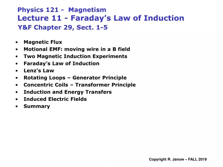
Physics 121 - MagnetismLecture 11 - Faraday’s Law of Induction Y&F Chapter 29, Sect. 1-5 • Magnetic Flux • Motional EMF: moving wire in a B field • Two Magnetic Induction Experiments • Faraday’s Law of Induction • Lenz’s Law • Rotating Loops – Generator Principle • Concentric Coils – Transformer Principle • Induction and Energy Transfers • Induced Electric Fields • Summary
Quick summary of magnetism so far Current-lengths in a magnetic field feel forces and torques Force on charge and wire carrying current torque and potential energy of a dipole Current-lengths (changing electric fields) produce magnetic fields Current loops are elementary dipoles Biot-Savart Ampere B outside a long straight wire carrying a current i: B at center of circular loop carrying a current i : Long Solenoid field: B inside a torus carrying B outside = 0 a current i : q B on the symmetry axis of a current loop (far field): Next: Changing magnetic flux induces EMFs and currents in wires (Faraday’ Law)
Surface Integral over open or closed surface Flux Unit: 1 Weber = 1 T.m2 q Electrostatic Gauss Law r B Magnetic Gauss Law Magnetic Flux: defined analogously to flux of electric field
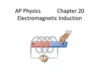
Changing magnetic flux causes an induced EMF (and possibly induced current) in a wire loop bounding the area. We really mean flux rather than just field is changing. Induced current creates it’s own induced B field (and flux) that opposes the changing flux(Lenz’ Law) Changing magnetic flux induces EMFs • EMF / current is induced in a loop if there is relative motion between loop and magnet - the magnetic flux inside the loop is changing. • Faster motion produces a larger current. • Induced current stops when relative motion stops (case b). • Induced current direction reverses when magnet motion reverses direction (case c versus case a) • Any relative motion that changes the flux works • Motion is one of several ways to change flux
CHANGING magnetic flux induces EMFs and currents in wires • Magnetic flux Area bounded by a loop • Faraday’s Law of Induction Key Concepts: • Lenz’s Law • Basis of generator principle: • Loops rotating in B field generate EMF and current in load circuit. • Lenz’s Law says external torque must do work to keep turning.
+ L v - FBD of free charge q in a wire + FIELD BOUNDARY Fm v Fe Eind - Motional EMF: Lorentz Force on moving charges in conductors • Uniform magnetic field points away from viewer. • Wire of length L moves with constant velocity v perpendicular to the field • Electrons in the wire feel a Lorentz force and migrate to the lower end of the wire. Upper end becomes positive. • Charge separation an induced electric field Eind exists inside wire • Charges come to equilibrium when the forces on charges balance: • Electric field Eind in the wire corresponds to potential difference Eindacross the ends of wire: • Potential difference Eind is maintained between the ends of the wire as long as it moves through the magnetic field. • Motion creates induced EMF. • Induced current flows only if the circuit • is completed.
Chain rule The rate of flux change = [field B] x [ rate of sweeping out area ] º = = dA/dt Ldx / dt Lv Rate of sweeping out area F d = = E BLv so ind dt Flux view gives same answers as motional EMF, and also works when there is no motion. Example: same problem as in last slide above FLUX F = BA. B is constant and uniform.
When there is no motion, flux change still explains induction Simple transformer: changing current in solenoid causes current to flow in outer coil. Field inside solenoid: Field outside solenoid = 0 at location of free charges in the 15 turn coil. So: Lorentz force can’t cause current there. Magnetic flux in solenoid also links to outer coil geometrically and is proportional to solenoid’s cross-section area (not the outer coil’s). So what causes induced current to flow in outer coil? Changing magnetic flux must create electric field at the outer coil location that induces current in outer coil (like other currents). Outer coil also creates its own field Bind, owing to induced current.
c b d a v • DOES CURRENT FLOW NOW? • Cross B-field boundary or B not uniform • Segment c-d now creates NO EMF • Segment a-b creates EMF as above • Un-balanced EMF drives current • just like a battery • or • FLUX is DECREASING c b v d a - - - - - - - - Which way does current flow? + + + + + + + + Examples: A rectangular loop is moving through a uniform B field • DOES CURRENT FLOW? • Segments a-b & d-c create equal but opposed motional EMFs in circuit. • No EMF from b-c & a-d • or • FLUX in loop abcd remains constant • Net flux is constant • No current flows CW
Induced current i2 creates it’s own induced field B2 whose flux F2 opposes the change in F1 (Lenz’ Law) i1 F2 = B2A F1 = B1A Ammeter Close S Open S later i2 i2 Induced Dipoles i2 Induced field and current directions • Replace moving magnet in sketch with circuit • No actual motion, switch closed • Current i1 creates field B1 (RH rule) • Flux is constant if current i1 is constant • Changing current i1 --> changing flux in loop 2. • Current i2 flows only while i1 is • changing (after switch S closes or opens)
“-” sign for Lenz’s Law uniform B Induced EMF (Volts) Rate of flux change (Webers/sec) EMF=0 B(t) slope EMF Example: B through a loop increases by 0.1 Tesla in 1 second: Loop area A = 10-3 m2 is constant & along field. Find the induced EMF uniform dB/dt front Current iind creates field Bind that opposes increase in B Faraday’s Law / Changing Flux Insert N for multiple turns in loop. Loop of any shape • Several ways to change flux: • change |B| through a coil • change area of a coil or loop • change angle between B and coil • e.g., rotating coils generator effect
+ L iind x - FEXT needed for constant speed isopposed to Fm with equal magnitude Drag force FM must act on slider • Due to the induced current: • Opposes the motion of the wire • External force FEXT is needed to • keep wire from slowing down Mechanical power supplied & dissipated: Slidewire Generator Example: slider moves, flux (loop area) grows • Induced EMF: • Slider: moving rightward at speed v • Uniform B field into the page • Loop area & FLUX are increasing • Lenz’s Law says induced field Bind • is out of page. • RH rule says induced current is CCW • Slider acts like a battery (Lorentz) • What about i2R? Can v be constant?
iind + L v - a) Find the EMF generated: iind DIRECTION: Bind is into slide, iind is clockwise b) Find the induced current if resistance R for the whole loop = 18 W: c) Find the thermal power dissipated: d) Find the power needed to move slider at constant speed !!! Power dissipated via R = Mechanical power !!! Slidewire Generator: Numerical Example B = 0.35 T L = 25 cm v = 55 cm/s
B Induced Current and Emf 11 – 1: A circular loop of wire is in a uniform magnetic field covering the area shown. The plane of the loop is perpendicular to the field lines. Which of the following will notcause a current to be induced in the loop? A. Sliding the loop into the field region from the far left B. Rotating the loop about an axis perpendicular to the field lines. C. Keeping the orientation of the loop fixed and moving it along the field lines. D. Crushing the loop. E. Sliding the loop out of the field region from left to right
front of loop The induced current and field try to keep the original magnetic flux through the loop from changing. front of loop front of loop Induced EMF drives induced current that inducesmagnetic flux opposite to the change in original magnetic flux. Lenz’s LawAgain induced dipole in loop opposes flux growth induced dipole in loop opposes flux decrease
v I Direction of induced current 11-2: A circular loop of wire is falling toward a straight wire carrying a steady current to the left as shown. What is the direction of the induced current in the loop of wire? • Clockwise • Counterclockwise • Zero • Impossible to determine • I will agree with whatever the majority chooses 11-3: The loop continues falling until it is below the straight wire. Now what is the direction of the induced current in the loop of wire? • Clockwise • Counterclockwise • Zero • Impossible to determine • I will oppose whatever the majority chooses
Generator Effect (Produce Sinusoidal AC) Changing flux through a current loop rotating with Rotation axis is out of slide q peak flux magnitude when wt = 0, p, etc. Induced EMF is the time derivative of the flux Eind peaks when dipole moment is perpendicular to Field. Eind is sinusoidal – polarity alternates over a cycle Maxima/minima when wt = +/- (2n+1)p/2 angular velocity w = 2pf in B field:
AC Generator No mechanical reversal of output E DC Generator Mechanical Reversal of output E
N turns E Numerical Example Stationary flat coil with N turns in B field Each turn increases the flux and induced EMF • N = 1000 turns • Varing B through coil decreases from +1.0 T to -1.0 T in 1/120 s. • Coil area A is 3 cm2 (one turn) Find the “back EMF” induced in the coil by it’s own changing flux • Changing magnetic flux creates induced E field along wire turns • that creates “back EMF”. • , Back EMF in wire turns drives current that creates magnetic field • opposing external field change. • The Lenz’s law effect is analogous to mechanical inertia.
SECONDARY PRIMARY Transformer Example Primary current is changing (for a short time) after switch closes. changing flux through primary coil ....that links to.... changing flux through secondary coil induces secondary current & EMF Iron ring strengthens flux linkage
conducting loop, resistance R Changing current I changing flux EMF is induced in wire loop: Bind Current induced in the loop is: If di/dt is positive, B is growing, then Bind opposes change and I’ is counter-clockwise What induces current i’ to flow outside the solenoid? • B = 0 outside solenoid, so it’s not Lorentz force acting on charges • An induced electric field Eind along the loop causes current to flow • It is caused directly by dF/dt within the loop path • Eind is there even without the outer wire loop (no current flowing) • E-field lines are loops that don’t terminate on charge. • E-field is a non-conservative (non-electrostatic) field inasmuch • as the line integral of E (D potential) around a closed path is not zero Generalized Faradays’ Law (hold loop path constant) Changing magnetic flux directly induces electric fields • A thin solenoid has n turns/unit length, cross section A • Zero B field outside solenoid (it is ideal) • Field inside solenoid: Flux linked to the wire loop:
For r > R (outside, circular integration path): For r < R (inside): The magnitude of induced electric field grows linearly with r, then falls off as 1/r for r>R Example: Generalized Faraday’s LawElectric field induced by a region of changing magnetic flux Find the magnitude Eind of the induced electric field at points outside and within the magnetic field region. Assume: • dB/dt = uniform across the circular shaded area. • E must be tangential: Gauss’ law says any radial component of E would require enclosed charge. • |E| is constant on any circular integration path due to cylindrical symmetry.
B = 0 B = uniform B = 0 v v v v v Expanded Lenz’s Law Example: As loop crosses a region of uniform magnetic field… The induced current and EMF create inducedmagnetic flux that opposes the change in magnetic flux that created them
AC Generator DC Generator Back-torque t=mxB in rotating loop, m ~ N.A.iind
EXTRA CREDIT Example: EMF generated by Faraday Disk Dynamo Conducting disk, radius R, rotates at rate w in uniform constant field B, FLUX ARGUMENT: evaluate areal velocity w, q + MOTIONAL EMF FORMULA: (work/unit charge) Radial conductor length EMF induced across length ds of moving conductor in B field (Equation 29.7) vXB looks like electric field to moving charge For points on rotating disk: v = wr, vXB = E’is radially outward, so is ds = dr current flows radially out dA = area swept out by radius vector in dq = fraction of full circle in dq x area of disk
Magnetic Flux: • Faraday’s Law: A changing magnetic flux through a coil of wire induces an EMF in the wire, proportional also to the number of turns, N. • Lenz’s Law: The current driven by an induced EMF creates an induced magnetic field that opposes the flux change. Bind & iind oppose changes in FB • Induction and energy transfer: The forces on the loop oppose the motion of the loop, and the power required to sustain motion provides electrical power to the loop. i1 • Transformer principle: changing current i1 in primary induces EMF and current i2 in secondary coil. i2 • Generalized Faraday Law: A changing magnetic flux creates non-conservative electric field. Recap: Faraday’s Law of Induction