Download
1 / 24
240 likes | 451 Views
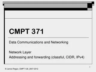
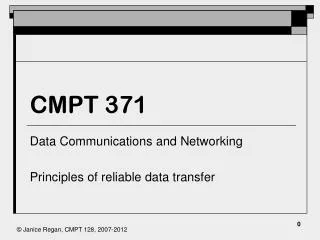
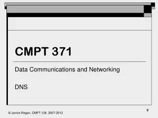
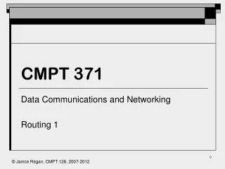
CMPT 371. Data Communications and Networking Network Layer ICMP and fragmentation. IPv4 Protocol Header. 0. 32 bits. 4. 8. 16. Header Length. Type of service. Version #. Datagram length (bytes) . Identifier . 13 bit fragmentation offset. Flags . TTL. Protocol

E N D
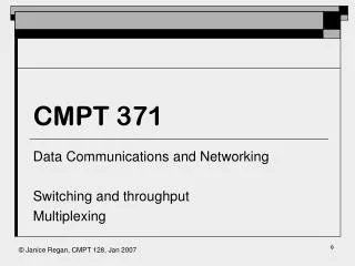
CMPT 371 Data Communications and Networking Network Layer ICMP and fragmentation
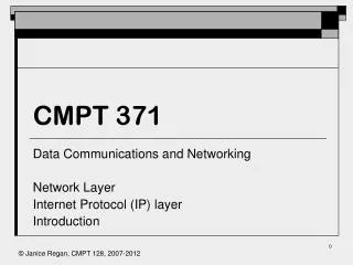
IPv4 Protocol Header 0 32 bits 4 8 16 Header Length Type of service Version # Datagram length (bytes) . Identifier . 13 bit fragmentation offset Flags . TTL Protocol transport layer Header checksum Source IP address Destination IP address Padding . Options (if any)
Header Fields (1) • Version(4 bits): Now 4 (IP v6 being phased in) • Internet header length or IHL( 4 bits): length of IP header in 32 bit words. Minimum is 20 octets, so header length would be at least 5. Used to locate the start of the payload • Type of service (8 bits): Contains bits to set priority (0 lowest to 7 highest) and to select routing based on optimization of reliability, precedence, delay or throughput parameters (TOS replaced by Differential Services)
Header Fields (2) • Total length (16 bits): This includes the header and the data payload. Packet length is measured in octets. Maximum length of a packet is 216 -1= 65,535 octets • Identification (16 bits): Identifies a particular datagram or packet. The same Identification is used for each fragment of a fragmented datagram. The final receiver will use the Identification for reassembly • Flags(3 bits): More bit, Don’t fragment bit, third bit is undefined
Header Fields (3) • Fragmentation offset (13 bits): Position of the fragment in the present packet within the unfragmented payload. (Must be a multiple of 64 bits from start of the unfragmented payload) • Time to live (8 bits): Measured in seconds, but must decrement by at least 1 at each intermediate station. Since transmission time in modern system are very rarely in excess of one second this is essentially a hop counter (Default 64) • Protocol (8 bits): protocol of next higher layer (transport layer) to receive data field at destination
Header Fields (4) • Header checksum (16 bits): ones complement of ones complement sum of all 16 bit words in header (assuming header checksum is zero).Reverified and recomputed at each intermediate station (IS) because TTL, some options and some other fields may change at each intermediate station. IP packet is discarded if checksum does not match. Note this is a checksum of the header not the entire datagram. • Source address (32 bits): IP address of originating station • Destination address (32 bits): IP address of final destination
Header Fields (5) • Options (variable): • Security, Strict source routing (specify all ISs), Loose source routing (Specify some ISs), record route (records address at each hop), timestamp (records address and timestamp at each hop) • Padding (variable) • To fill to multiple of 32 bits long after options added • Data field • Carries user data from next layer up • Integer multiple of 8 bits long (octet) • Max length of datagram (header plus data) 65,535 octets
IP Fragmentation (1) • Uses fields in header • Data Unit Identifier (ID): uniquely identifies end system originated datagram and contains • Source and destination address • Protocol layer generating data (e.g. TCP) • Identification supplied by that layer • Data length: Length of user data in octets (datagram length – header length) • Fragmentation Offset: Position of fragment of user data in original datagram, (offset from start of original datagram) in multiples of 64 bits (8 octets) • More flag: Indicates that this is not the last fragment
IP Fragmentation (2) • Copy the header frame of the incoming datagram into each fragment • Divide the incoming user data field into equal parts along 64bit boundaries (last fragment may be shorter). Length of each equal part is MTU • For of each datagram except the last, set Data Length to the length of each data fragment and set more flag to 1. Add the length of the previous data segment in octets to the Offset. • For the last datagram set Data Length to the length of the remaining data, Add the length of the previous data segment in octets to the Offset.
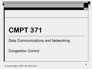
Fragmentation: example 1 IP header UDP header IP data 612 octets UDP header IP header 208 octets IP header 208 octets IP header 196 octets offset=0 more=1 offset=208/8=26 more=1 offset=52 more=0
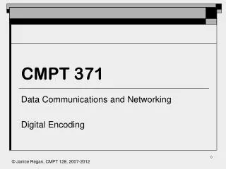
Fragmentation: example 1 IP header TCP header IP data 1400 octets TCP header IP header 600 octets IP header 600 octets IP header 200 octets offset=0 more=1 offset=600/8=75 more=1 offset=150 more=0
Dealing with Failure • Re-assembly may fail if some fragments get lost • Need to detect failure • Re-assembly time out • Assigned to first fragment to arrive • If timeout expires before all fragments arrive, discard partial data • Use packet lifetime (time to live in IP) • If time to live runs out, kill partial data • Fragmentation is needed but Don’t fragment bit is set: packet is dropped
Dealing with IP errors • IP datagram delivery (network level) has a header checksum to detect transmission errors in the IP header • TCP has a checksum which covers the TCP header, pseudo header and data • Higher level protocols (for example TCP) also handle more types of errors • Higher level protocols need to be informed that the errors have occurred in order to handle them more efficiently that with only timeouts and retransmissions • Within IP need an error reporting mechanism to report such errors to TCP, one such mechanism is the ICMP protocol.
Why fragment • The maximum size of a TCP (or UDP) segment can be configured for each network • Therefore different networks can have different MSS (maximum segment size) • When a segment from a network with a larger MSS must pass through a network with a smaller MSS the segment must be broken into parts small enough to pass through the network with the smaller MSS • The parts will be reassembled at the destination • any intermediate network may have multiple routers, • not all segments will leave the intermediate network through the same router, so they cannot be reassembled as they leave the intermediate network
Errors in Packet Switching Networks • Possible causes of errors include • Hardware failure • Network congestion • Inability to fragment (DF set) • Routing loops • Unavailable host (disconnected or failed) • Queue overrun on routers • IP offers best effort delivery, it needs a mechanism to inform the source of packets dropped because of errors (except transmission errors). In the remainder of this lecture errors will mean errors not cause by transmission impairments
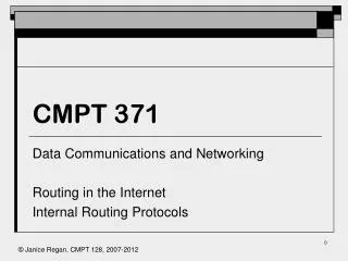
ICMP message format • Internet Control Message Protocol (RFC792) • There are several types of ICMP messages designed to report different types of errors • Each ICMP message has its own format, but all start with the same three fields • A type field (1 octet) indicating which type of ICMP message follows • A 1 octet code following the type that further defines the message (see text for list) • For example type specifies destination unreachable, code specifies router or host • The 3rd common field is a 2 octet checksum.
ICMP Message Types Comer 2000:
What ICMP messages do • Time exceeded • Lifetime of datagram expired • Parameter problem • IP header parameter cannot be interpreted • Timestamp/timestamp reply • Measures transmission time (not time in queue) for strict source routing • Redirect message • Sends router a ‘better’ route to the destination that it currently has • Router discovery / solicitation • Can be used by a booting host on the network to find the routers • wait for discovery message which lists routers and is periodically transmitted • ask for immediate discovery message by sending a solicitation message
ICMP Echo Request/Reply • Echo request is sent by the ping command to test for reachability • Echo reply is sent in response to a received echo reply to confirm reachability • Type: request 8, reply 0, Code 0 : no additional qualifying codes • Identifier and sequence number are optional, they can be used to match replies with requests • The optional data in a echo request must be returned in the resulting echo reply • Linux ping has a record route and a timestamp option
traceroute The unixtraceroute command is an example of the use of the time exceeded message A UDP packet with a hop count of 1 is sent The first router reached sends back a time exceeded message, identifying itself A packet with a hop count of 2 is sent The second router in the path sends back a time exceeded message identifying itself This is repeated, incrementing the hop count by 1 until the packet reaches its destination Ubuntu sends 3 copies of each packet sent in the description above
ICMP destination unreachable • Sent when a router or host cannot deliver a datagram due to an identified failure (not all failures are identified) • Can be disabled, not all hosts or routers will send ICMP messages • The codes indicate what destination could not be reached and why (see table in text) • The header and datagram information is provided to identify the packet needing retransmission (port numbers and sequence number for TCP UDP)
ICMP Source Quench Message • Used to help control congestion • When a packet must be dropped due to congestion a source quench packet may be sent to the source • When the source receives a source quench message it may reduce the rate at which it transmits to the network • 1 quench message per round trip travel time should cause change