Download
1 / 28
290 likes | 311 Views
Seminar presentation Braking system, tyre. Braking system. Brake is a device used for slowing ,stopping & controlling the vehicle. Braking operation based on kinetic energy of vehicle is to converting into heat, which dissipated into atmosphere.

E N D
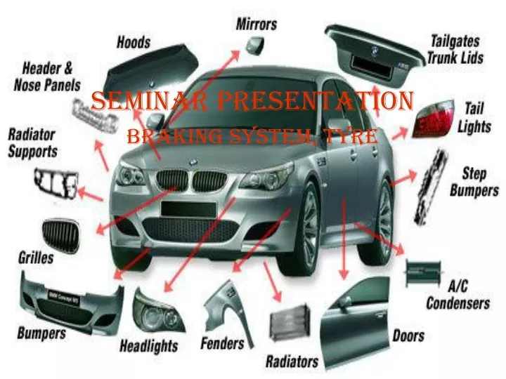
Seminar presentation Braking system, tyre
Braking system • Brake is a device used for slowing ,stopping & controlling the vehicle. • Braking operation based on kinetic energy of vehicle is to converting into heat, which dissipated into atmosphere. • While driving the vehicle, torque of the engine produces The tractive effort due to periphery of driving vehicle. • When the brakes are applied it produces negative tractive effort on wheel. • While, this help to slow down an vehicle
Main functions of braking system • To stop the vehicle safely in shortest possible distance in case of emergency. • To control the vehicle when it is descending along the hills • To keep the vehicle in desired position after bringing in at rest
HYDRAULIC BRAKING SYSYTEM • construction • hydraulic braking system is mainly confined with “brake fluid” this fluid consist of Alcohol,castor oil & glycerin.hydraulic braking system has following components. master cylinder,brake pedal,wheel cylinder,brake drum,retracting spring,brake shoe etc.
Working System • The brake pedal is connected to the master cylinder by means of piston for application of brake driver presses the brake pedal, which moves the master cylinder. • In master cylinder pressure is instantly transferred to all four wheels. The brakes shoe moves against the brake drum to apply brakes. • When driver releases the brake pedal, the master cylinder piston returns to its original position due to return springs, dropping fluid pressure. Brake shoe retracting spring pulls the brake shoe from drum to their original position & brakes are released. • ROLE OF MASTER CYLINDER: • TO BUILD THE hydraulic pressure required to operate the system. • To bleed or force air out of brake line & wheel cylinder. • A to act reservoir to maintain a constant volume of fluid in system • ADVANTAGES OF HYDRAULIC BRAKE • simple in construction :Mechanical joints, linkages & cam are eliminated. • Equal braking system: the brake fluid must exists equal pressure. • Disadvantages of Hydraulic Brake • Fails whole system at one time: if there is leakages in system, all four brakes are fail at one time due to loss of fluid pressure. This difficulty can be eliminated with use of tendum master cylinder
CONSTRUCTON • Pneumatic BRAKES ARE OPERATED BY MEAns of Air pressure engine to air and stores in air reservoir.the compressed air enters in wheel cylinder to push diaphragm • The pneumatic braking system consists as : • Air compressor, unloader valve, resevoir, brake valve, brake chamber ,quick release valve, Relay valve etc.
Working of Pneumatic Braking System Air Compresor Its composes of generally Build the air pressureby driven of engine. UNLOADER VALVE: ITS IS DEVICE MAINTAIN CONSTANT PRESSURE IN RESERVOIR.the excess of pressure is safely removed. Reservoir: it’s a tank in which high pressure air is stored Brake Valve: its is located between air reservoir and brake cylinder RELAY VALVE: IT IS VALVE KEPT IN BETWEEN BRAKE CHAMBER & AIR CHAMBER FOR CONTROLLING THE AIR CHAMBER
Mechanical Braking System • Classification • Mechanical Braking System, brakes are available in following construction 1.Drum type 2.Disc type • Drum type Brake There are generally of two types • Internal expanding drum brake. • External expanding drum brake.
Internal Expanding Brake Drum • Construction. • In Internal Expanding Drum Brake consist of leading shoe, anchor, adjustor, Heel of shoe, trailing shoe, brake retracting spring brake shoe, brake shoe,toe shoe etc. • In internal expansion b raking system brake liners are expands internally • Its consist of stationary plate,two shoes hinged at anchor pins, and cam system to expand the shoe and a retracting spring.
Working system of internal braking system • Internal expanding braking system consist of brake linings are fixed at outsides when brakes are applied the cam is turned, the shoe with brake lining are forced against the Drum. • This Causes brake lining creates friction between the rotating drum and expanding shoes. • This force of friction opposes the rotating drum, thereby will leads to slowing down the vehicle. • When brake is released Retracting springs brings the shoe back towards its original position.
External contracting brake drum • Construction • IN external contracting brake drum has brake drum is used for only parking purpose .this system consist of Drum, brake & lining, operating lever with adjusting lever and push rod with returning spring. • External braking system is model braking system used to operate in floor mills, various types of electrical components. the following various types of parts is applied on brake drum..
WORKING OF EXTERNAL CONTRACTING BRAKE DRUM • The working system of external braking system, when push rod is operated by hand or foot operated lever, then the lined brake drum is fitted around the drum is tightened to lock or slow down the drum. • When the brake is released the return springs bring the band brake back to its initial position. • The system remains air opened; therefore dirt is being accumulated between the rubbing surfaces, which reduces the efficiency…
Disc Type Brake • CONSTRUCTION • DISC Brake consist of cat iron disc bolted to the wheel hub and an stationary housing called “caliper”. The caliper is connected with some stationary part of position of vehicle, like stub or axle on of wheel of connecting rod . • The piston rod is connected in between which has friction pad is being held by an piston pins, springs etc.
Working of Disc brake • The brakes are operated when friction is being created on friction pads by forced applying on it against the disc .the forces created on its is hydraulic pressure from master cylinder, thereby an engaging the braking system. • When the hydraulic braking pressure is applied on piston will engaged an released bar due to pressure. • When pressure is released piston will regain its original position. Here friction pad works on main fundamental working process. • “CALIPER “ is added on system to balanced two calipers by diagrammatically opposite to each to other. In this way braking torque is reduced. • Advantages of Disc Brake • Better heat dissipation as braking torque on surface of exposed air. • Adjustment of pads is automatic • Renewal of pad is quick and easy. • Disadvantages of Disc Brake. • In comparison of brake drum of similar capacity, rate pad wear is more. • The HAND BRAKE MECHANISM IS NOT SO CONVINENT.
ANTILOCKING BRAKING SYSTEM {abs}SOURCE: Internet • Anti-lock braking system (ABS)is an automobile safety system that allows the wheels on a motor vehicle to maintain tractive contact with the road surface according to driver inputs while braking, preventing the wheels from locking up (ceasing rotation) and avoiding uncontrolled skidding. It is an automated system that uses the principles of threshold braking and cadence braking which were practiced by skillful drivers with previous generation braking systems. It does this at a much faster rate and with better control than a driver could manage • ABS generally offers improved vehicle control and decreases stopping distances on dry and slippery surfaces for many drivers; however, on loose surfaces like gravel or snow-covered pavement, ABS can significantly increase braking distance, although still improving vehicle control.
Working of Anti Braking System • The anti-lock brake controller is also known as the CAB (Controller Anti-lock Brake). • Typically ABS includes a central electronic control unit (ECU), four wheel speed sensors, and at least two hydraulic valves within the brake hydraulics. The ECU constantly monitors the rotational speed of each wheel; if it detects a wheel rotating significantly slower than the others, a condition indicative of impending wheel lock, it actuates the valves to reduce hydraulic pressure to the brake at the affected wheel, thus reducing the braking force on that wheel; the wheel then turns faster. Conversely, if the ECU detects a wheel turning significantly faster than the others, brake hydraulic pressure to the wheel is increased so the braking force is reapplied, slowing down the wheel. This process is repeated continuously and can be detected by the driver via brake pedal pulsation. Some anti-lock systems can apply or release braking pressure 15 times per second. Because of this, the wheels of cars equipped with ABS are practically impossible to lock even during panic braking in extreme conditions • Modern ABS applies individual brake pressure to all four wheels through a control system of hub-mounted sensors and a dedicated micro-controller. ABS is offered or comes standard on most road vehicles produced today and is the foundation for electronic stability control systems, which are rapidly increasing in popularity due to the vast reduction in price of vehicle electronics over the years
Construction of Anti Braking System • There are four main components of ABS: speed sensors, valves, a pump, and a controller. • Speed sensors • The anti-lock braking system needs some way of knowing when a wheel is about to lock up. The speed sensors, which are located at each wheel, or in some cases in the differential, provide this information. • Valves • There is a valve in the brake line of each brake controlled by the ABS. On some systems, the valve has three positions: • In position one, the valve is open; pressure from the master cylinder is passed right through to the brake. • In position two, the valve blocks the line, isolating that brake from the master cylinder. This prevents the pressure from rising further should the driver push the brake pedal harder. • In position three, the valve releases some of the pressure from the brake. • Pump • When the ABS system operates the brake lines lose pressure. The pump re-pressurizes the system. • Controller • The controller is an ECU type unit in the car which receives information from each individual wheel speed sensor, in turn if a wheel loses traction the signal is sent to the controller, the controller will then limit the brakeforce (EBD) and activate the ABS modulator which actuates the braking valves on and off.
USES • The controller monitors the speed sensors at all times. It is looking for decelerations in the wheel that are out of the ordinary. Right before a wheel locks up, it will experience a rapid deceleration. If left unchecked, the wheel would stop much more quickly than any car could. It might take a car five seconds to stop from 60 mph (96.6 km/h) under ideal conditions, but a wheel that locks up could stop spinning in less than a second. • The ABS controller knows that such a rapid deceleration is impossible, so it reduces the pressure to that brake until it sees an acceleration, then it increases the pressure until it sees the deceleration again. It can do this very quickly, before the tire can actually significantly change speed. The result is that the tire slows down at the same rate as the car, with the brakes keeping the tires very near the point at which they will start to lock up. This gives the system maximum braking power. • When the ABS is in operation the driver will feel a pulsing in the brake pedal; this comes from the rapid opening and closing of the valves. This pulsing also tells the driver that the ABS has been triggered. Some ABS systems can cycle up to 16 times per second.