Download
1 / 18
180 likes | 186 Views
PARIS - A CONCEPT DESIGN FOR A VERY LOW FREQUENCY SATELLITE BASED RADIO INTERFEROMETER Divya Oberoi 1 and Jean-Louis Pin ç on 2 1 MIT-Haystack Observatory 2 Laboratoire de Physique et Chimie de la Environnement-CNRS, Orl é ans, France

E N D
PARIS - A CONCEPT DESIGN FOR A VERY LOW FREQUENCY SATELLITE BASED RADIO INTERFEROMETER Divya Oberoi1 and Jean-Louis Pinçon2 1MIT-Haystack Observatory 2Laboratoire de Physique et Chimie de la Environnement-CNRS, Orléans, France doberoi@haystack.mit.edu jlpincon@cnrs-orleans.fr Laboratoire d’Etudes Spatiales et d’Instrumentation (LESIA) from Paris-Meudon Observatory, France Nancay Radio Astronomy Station, France
The Plan • Objectives • VLF Radio Astronomy - some salient features and their implications • Straw-man concept • Data analysis strategy • Constellation configuration • Choice of orbit • Bottle-necks • Conclusions
The Objectives • A fresh look at the design of a VLF Radio Astronomy • Think of what we would like, as opposed to what we can get today • Rather than adapt and extendconventional RA techniques, try to come up with solutions tailored to VLF RA • Exploit the recent advances in technology - most importantly in hardware and computing power • Appropriate time forPrepAration for Radio Astronomy In Space(PARIS), a feasibility study for a satellite borne interferometer operating below the ionospheric cut-off frequency
VLF Radio Astronomy - some salient features • 1. Extremely bright galactic background (~0.1 - >10 x 106 K) Dulk et al. A&A, 365, 2001
2. Size of the receptor elements < l * An omni-directional reception pattern SIRA will receive signal from Sun and everything else as well 3. Sun is brighter than the Gal BG, but is only an ~ arc min2 in size n Quiet Sun Gal BG MHz Jy Jy 30 ~103 ~3x10⁶ It only gets worse at lower n Erickson et al., Solar Physics, 54, 1977
The Implications The flux received from the entire FOV contributes to Tsys Only the part which is mapped contributes to Tant S/N on a visibility measurement ~ Tant / T sys It will be best to map the entire FOV ~4p sr * A full blown 3D Fourier inversion will be required * Optimise the u-v-w coverage as opposed to only u-v coverage * Compute visibilities over sufficiently bandwidths so that the signal coming from even 90o from the phase center does not get decorrelated
VLF Radio Astronomy salient features ... • 4. Transmitting Nyquist sampled time series is extremely telemetry intensive. • RF bandwidth andno. of bits per sample are reduced to fit inside the available telemetry bandwidth. For instance the ALFA proposal offered a max of 125 kHz of RF bandwidth per poln ,with 1 bit/sampleand used a total of 8 Mbps. • To increase the scientific returns it is essential to reduce the data volumes => compute visibilities on-board in real time and average them over time and frequency • 2-3 orders of magnitudes of data compression is very realistic!
The Straw-man concept • A heterogeneous constellation of 16 three axis stabilised micro- satellites (120 instantaneous baselines) • Frequency range : 0 - 40 MHz • Three, mutually orthogonal, short dipoles per satellite • Maximum baseline : 80 - 100 km • Resolution : ~15’ at 1 MHz and ~0.5’ at 30 MHz • Essentially a digital instrument with very high reliance on Digital Signal Processing technology • Nyquist sample the entire 40 MHz RF band using 14-16 bits • (aim ~90 dB dynamic range)
The Straw-man concept ... • On-board computing - distribute as much of the computing load as possible • On-board constellation members • A two stage FFT engine will transform the Nyquist sampled time series into spectra : 1st stage - 195 kHz, 2nd stage 1 kHz spectral channels • Prominent RFI will be detected after first FFT and RFI affected data will be rejected • The selected 14-16 bits/sample part of the spectrum will be resampled at 1-2 bits/sample and transmitted to the mother satellite
The Straw-man concept ... • On-board the Mother satellite • The data streams from all the other 15 satellites will be received and visibilities will be computed • 3x3 = 9 visibilities will be computed per physical baseline • The visibilities will be averaged over frequency and time and transmitted to the Earth • Advantage - possible to distribute RF bandwidth over the entire 40 MHz of RF bandwidth in an arbitrary manner • The clock needed for synchronisation will be distributed using the station keeping sub-system charged with providing real time satellite positions. Conventional LO not required
The data analysis strategy • Desire • Sun - image at time scales short enough to catch the action • Rest of the sky - combine the data collected over the life time of mission to image the sky • Problems • Not possible to simply image the Sun and forget the rest • Apparent position of Solar system sources change rather rapidly
The data analysis strategy ... • Our approach • Solar studies - subtract the contribution of the rest of the sky using a Global Sky Model (GSM), which keeps getting updated during the mission lifetime • All other studies - subtract a time dependent model of the Sun • Overlap with LOFAR frequency range, to make use of the detailed GSM at the high frequency end • Use it as an anchor point and boot-strap to lower frequencies • Archive the visibility data and re-analyse it as GSM improves
The Constellation configuration • Objectives • Optimise snap shot low resolution imaging of the Sun • Optimise long term high resolution synthesis imaging of the rest of the sky Sun 8-10 km 80-100 km
The Constellation configuration... • Drawback - all the long baselines lie in a plane => no high resolution imaging possible in the direction of the plane • Solution? - remove a few satellites from the Cigar and place them suitably • Reduces the no. of baselines available for high time resolution Solar imaging dramatically • Does not provide enough sampling in the perpendicular direction • A dynamic configuration in the perpendicular direction will be useful
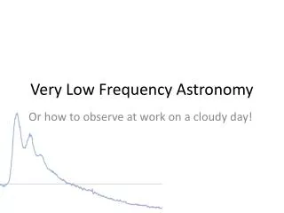
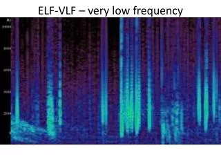
The choice of orbit • Formation flying requirement => low differential gravity over the constellation length scales • Even 105 km from the Earth, man made Radio Frequency Interference is a significant bother. Becomes less intense with increasing distance and its directivity also makes it easier to tackle. A typical frequency vs time plot from the WIND/WAVES. The colour scale is in dB relative to the Galactic Background. Commercial short wave bands are also shown alongside. Kaiser et al., Geophys. Res. Let., 23, 1996 14 MHz 1
The choice of orbit... Distant Earth Orbits are the orbits of choice - Distant Retrograde or Prograde orbitsat a distance of about a million km from the Earth andhalo orbits around the L1 Lagrange point Real time satellite position accuracy requirements ~0.75 m (l/10 at 40 MHz) - do not seem to pose a problem Formation flying requirements are very flexible - we do not need to place the satellites in precise configuration, they can drift about by 10% or so… we only need to know where they are
The telemetry requirements Each satellite transmits@6 Mbps/MHz RF bandwidth to the Mother satellite (1 bit/sample, 3 dipoles) Mother satellite to the Earth Dn (kHz) Dt (sec)Mbps/MHz ALFA/SIRA 1 1 18.0 (8.0) 64 Mbps/MHz 10 10 0.18 (0.08) (1 bit/sample) (16 bits/complex visibility, 9 visibilities/baseline) The major bottlenecks • Intersatellite telemetry • - Reception by Mother : 90 Mbps/MHz RF bandwidth • satellite • Meeting the on-board computing requirements • - Possible on ground, just within the power budget • space qualified technology not there yet
Conclusion • We are at the brink of a quantum leap in the capabilties of a VLF interferometer • There are bottle necks to be overcome, but they lie in areas where one can expect rapid progress • The wait, in my opinion, will be well worth the returns • Need numbers for performance parameters compatible with the science goals... to guide the design to make the right trade-offs