Download
1 / 33
350 likes | 378 Views
Explore the fundamentals of IPv4 and IPv6, the hierarchical addressing system, subnet masks, CIDR, routing tables, and the transition to IPv6 to address the challenges faced by the current IPv4 protocol.

E N D
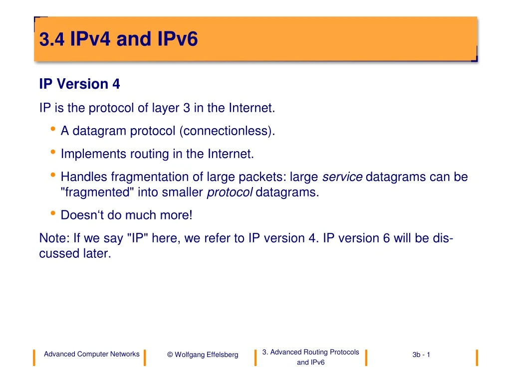
3.4 IPv4 and IPv6 IP Version 4 IP is the protocol of layer 3 in the Internet. • A datagram protocol (connectionless). • Implements routing in the Internet. • Handles fragmentation of large packets: large servicedatagrams can be "fragmented" into smaller protocoldatagrams. • Doesn‘t do much more! Note: If we say "IP" here, we refer to IP version 4. IP version 6 will be dis-cussed later.
0 1 16 24 31 8 class A 0 NetID HostID class B 1 0 NetID HostID class C 1 1 0 NetID HostID 1 1 1 0 group address class D Addressing in the Internet (1) • An IP address is a hierarchical address with net and host identification num-ber (netid and hostid). There are three formats for subnetworks of different sizes as well as a format for multicast:
Addressing in the Internet (2) • Strangely common is a decimal way of writing with one number per byte. • Examples: • 10.0.0.0 for Arpanet • 128.10.0.0 for a large Ethernet LAN • 192.5.48.0 for a small ring LAN • (hostid = 0 marks a network of one host)
CIDR – Classless Interdomain Routing • Class B addresses were used up quickly and became a bottleneck in the Internet. Therefore, the IETF introduced CIDR in 1993 (RFC 1519). It allows an arbitrary subset of bits to be used for the hostid, with the rest being the netid. • For example, imagine a company with 2000 hosts. With the old „classful“ scheme it would require a class B address but would only use 2000 out of the 65536 addresses. With CIDR, we would reserve an address space in the form a.b.c.d/21, with 21 bits for the netid and 11 bits for the hostids. • CIDR is now implemented in all routers.
Subnet Masks • Large campuses might have many subnetworks with routers in between, so they would require multiple IP subnet id‘s. But that is inconvenient: it blows up routing tables and makes routing inefficient. • This problem is solved by introducing subnet masks. A subnet mask deter-mines the part of the IP address that is used internally as the network id. All hosts in that subnet can be reached directly, without going through the de-fault router. • Subnet masks are written in decimal notation, like IP addresses. Usually they begin with a sequence of 1’s, followed by a sequence of 0’s.
NetID HostID class B address 111111111111111111110000 00000000 subnet mask (255.255.240.0) NetID subnetID HostID subnetted address Subnet Mask Example
Subnet Example (1) • Subnet mask: 255.255.240.0 H1: 134.155.92.20 R1: 134.155.80.200 • H2: 134.155.92.21 H3: 134.155.50.05 H1 Computing Center H2 R1 H3 Building A 5
Subnet Example (2) • The sending host H1 computes the AND of the destination IP address and the subnet mask as well as the AND of his own IP address and the subnet mask. If these are the same he knows that the destination host can be reached directly, without going through the default router. • In our example: • Subnet mask: 255.255.240.0 1111 1111 1111 1111 1111 0000 0000 0000 • SourceID H1: 134.155.92.20 1000 0110 1001 1011 0101 1100 0001 0100 • AND: 1000 0110 1001 1011 0101 0000 0000 0000 • SourceID H2: 134.155.92.21 1000 0110 1001 1011 0101 1100 0001 0101 • AND: 1000 0110 1001 1011 0101 0000 0000 0000 same subnet • SourceID H3: 134.155.50.05 1000 0110 1001 1011 0011 0010 0000 0101 • AND: 1000 0110 1001 1011 0011 0000 0000 0000 different network • -> The IP packet with destination H3 goes through the default router.
Usage of Subnetworks • Subnet masks are only relevant for outgoing traffic. Traffic from remote loca-tions goes directly to the class B address (or the CIDR address) of the desti-nation host.
IP Version 6 (IPv6) • Motivation: Addressing problems • The IP address range will be exhausted soon. • Class B addresses now are already almost exhausted. • CIDR (classless inter-domain routing) was introduced as a short-term solution. • Routing tables grow very fast: an addressing hierarchy with additional levels becomes necessary. • (mobile) Internet devices in cars, households etc. 10 billion humans in the year 2020 and 100 IP addresses per person are not unrealistic. • Solution • New IP protocol version 6 (IPv6) with a very larger address space is to replace IPv4. *) I would like to thank Professor Torsten Braun (University of Bern) for letting me use his slides on IPv6.
History of IPv6 • 1992 • IETF publishes Call for Proposals for an “IP next generation“ (IPng) as successor of IPv4 • 1994 • SIPP (simple Internet Protocol plus) is suggested as basis for the new IPng • 1995 • Internet Draft "Internet Protocol, Version 6 (IPv6)" becomes “proposed standard" (9/95) and RFC1883 (12/95). First prototype implementations. • 1996 • Establishment of the IPv6 Backbone (6Bone) between research labs, first products in the market. • 1998 • RFC 2460, Draft Standard • 2008 • Implemented in most products but not yet widely used by ISPs.
Characteristics of IPv6 (1) • Extended addressing capabilities • 128 bit addresses (one address per atom in the universe, 1023 addresses per m2 of the surface of the earth!) • Address hierarchy levels for IP (registration instance, provider, sub-scriber, subnetwork, interface) • automatic address configuration built into the protocol (similar to DHCP) • New IP Header Format • simplified, minimum IP header • improved support of new options and extensions: extension header • segmenting and reassembling fragments is done in end systems only
Characteristics of IPv6 (2) • Quality of Service Support • “flow labels“ allow the marking of application data flows on the IP level • “traffic classes“ for Differentiated Services • Multicast Integration • pre-defined groups of multicast for control functions • IGMP (Internet Group Management Protocol) integrated into ICMP (Internet Control Message Protocol) • special multicast address format • All routers and end systems support multicast; no special measures are necessary for multicast connections (such as tunnels). • IP Security • Authentication and encryption are integrated.
Location topology Public topology 3 13 8 24 16 001 TLA ID res. NLA ID SLAID Interface ID Global Unicast Addresses • Top Level Aggregation (TLA) • large Internet service provider (ISPs) with transit networks to which other ISPs are attached • Next Level Aggregation (NLA) • Organizations on a lower level • several NLA levels are possible • Site Level Aggregation (SLA) • individual addressing hierarchy of an individual organization
Backbone Provider A Backbone Provider C Exchange Point Backbone Provider B Backbone Provider D Provider B.A Provider D.A Subscriber D.1 Subscriber B.A.1 Provider B.A.A Subscriber D.A.1 Subscriber D.A.2 Subscriber B.A.A.1 Subscriber B.A.A.2 TLA, NLA and SLA
Special Unicast Addresses (1) • Local Unicast Addresses • Link local • for configuration purposes or IP networks without a router • only valid on the local link • Prefix: 1111111010::/64 • Site local • for IP networks that are not attached to the Internet • will go over routers but will not leave the site • when connecting a site to the global Internet only the address prefix (1111111011::/48) must be replaced • SLA ID and interface ID remain unchanged
Special Unicast Addresses (2) • Compatible Unicast Addresses • IPv4 compatible • Prefix (96 0-bits) + IPv4 address
renamed precedence class total length payload length time to live hop limit protocol next header cancelled shifted into the extension header Version Hdr Len Prece- dence ToS Total Length Identification Flags Fragment Offset Time To Live Protocol Header Checksum Source Address Destination Address IPv4 Header 20 Bytes, 13 fields
Vers. Class Flow Label Payload Length Next Header Hop Limit Source Address Destination Address IPv6 Header 40 Bytes, 8 fields
Concept of Extension Headers • Small Standard Header and Extension Header(s) • small minimal header of constant size • additional extension headers, depending on the requirements of the application or the network characteristics • future extensions and options can be added easily
IPv6 Header next header = TCP TCP Header + Data IPv6 Header next header = Routing Routing Header next header = TCP TCP Header + Data IPv6 Header next header = Routing Routing Header next header = Fragment Fragment Header, next header = TCP TCP Header + Data Examples of Extension Headers
3A01:203:405:1::/64, 3A01:203:405:1::1 FE80::C:D:1 3A01:203:405:1::C:D:1 3A01:203:405:1::1 Stateless Automatic Address Configuration • The router periodically broadcasts IP parameters to the multicast group of all hosts (“router advertisement"), i. e., with the prefix of the local link. • Each host can send a “router solicitation" to the multicast group of all routers; a direct “router advertisement” of the router will follow. • There is also a “stateful autoconfiguration” in IPv6.
Transition Strategies • IPv4 and IPv6 systems must be able to communicate with each other. After a transitional phase only a few pure IPv4 systems should remain. • Basis mechanisms • Dual protocol stacks • IPv6 over IPv4 tunneling • The IPv6/IPv4 header translation is necessary only for communication between pure IPv4 nodes and pure IPv6 nodes. • More complex mechanisms • Stateless IP/ICMP Translation (SIIT) • No Network Address Translation (NNAT) • Network Address Translation / Protocol Translation (NAT/PT)
Applications Socket Interface UDPforIPv4 TCPforIPv4 UDP for IPv6 TCP for IPv6 IP v4 IPv6 Network Dual Protocol Stacks • Dual protocol stacks • UDP/IPv4 and UDP/IPv6 • TCP/IPv4 and TCP/IPv6 • All IPv6 systems will also have an IPv4 stack during the transition phase.
0 ... 0 0 ... 0 IPv4 address IPv4 Compatible Address • An IPv6 address is built on the basis of the old IPv4 address. • Used by IPv6 systems for communication with other IPv6 systems via automatic tunnels. • Only useful in the early transition phase; the advantages of IPv6 addressing are lost.
Tunneling • Tunneling is the wrapping of an IP packet into another IP packet with a new destination IP address. At the end of the tunnel, the internal IP packet is un-wrapped again. In this way, the original IP packet can be "tunneled“ through subnetwork distances which it could not pass otherwise. • IP tunnels are usually configured manually.
IPv4 Router Configured Tunnel (Host Router or Router Router) Automatic Tunnel (Router Host, Host Host) IPv6 Tunnels IPv4 Router
Stateless IP/ICMP Translation (SIIT) • Requires the dynamic allocation of IPv4 addresses! • Supports communication between pure IPv6 systems and pure IPv4 systems. • Stateless translation of IPv4/IPv6 and ICMPv4/ICMPv6 packets • No translation of routing headers, hop-by-hop options and destination options.
IPv6 Header Fragment Header IPv4 Header Transport Header Transport Header Data Data Illustration of SIIT IPv6 Host IPv4 Host SIIT
Effects of IPv6 on Other Protocols • Routing Protocols • Handling of longer addresses • Transport Protocols • Reduced maximum user data length because of the larger IP header. • The fact that there is no checksum in the IPv6 header requires the implementation of the checksum in UDP (now mandatory) and in TCP. • TCP currently does not support an IP address change during an existing TCP connection.
Conclusions • IP Version 4 is the layer-3 protocol of the Internet. It is a datagram protocol (connectionless). It is very widely used today. • IP Version 6 is its more modern and more powerful successor, including bigger addresses, extension headers, multicast support, some QoS sup-port and auto-configuration. It is not yet very widely used, mainly because the transition from IPv4 is difficult to manage for ISPs.