Download
1 / 26
260 likes | 423 Views
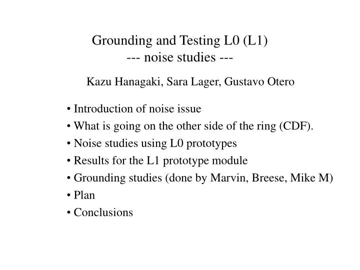
Grounding and Testing L0 (L1) --- noise studies ---. Introduction of noise issue What is going on the other side of the ring (CDF). Noise studies using L0 prototypes Results for the L1 prototype module Grounding studies (done by Marvin, Breese, Mike M) Plan Conclusions.

E N D
Grounding and Testing L0 (L1)--- noise studies --- • Introduction of noise issue • What is going on the other side of the ring (CDF). • Noise studies using L0 prototypes • Results for the L1 prototype module • Grounding studies (done by Marvin, Breese, Mike M) • Plan • Conclusions Kazu Hanagaki, Sara Lager, Gustavo Otero
Introduction of Noise issues for L0 • Goal: S/N>10 after 15(6.5-11?) fb-1. • Internal contribution: capacitive load by the long analog flex cable. • External contribution: RF pickup, capacitive coupling… unfortunately the analog cable works as antenna. • A few slides to show the current CDF situation.
Noise in terms of Capacitive Load Total noise estimates VS total capacitance (Csi + Ccable) S/N=10 CSi Ccable S/N=10 after 15fb-1 Ccable < 23pF for 43.5cm long cable Ccable < 0.53pF/cm
cable1 cable2 Lesson from CDF (Pickup on Signal Cables) • Noise picked up by analog signal cables • Effects are seen at edges of cables, within one sensor • Both coherent and incoherent sources • Noise shapes • Pedestal shifts Hybrids Wide Sensors Signal Cables Narrow Sensors
Lesson from CDF (Study of Pickup) • L00 module in a well-grounded faraday cage • Insert a noise source (waveform generator) • Vary amplitude, frequency, geometry, grounding, shielding, state of SVX3D chips when acquiring, etc. • Conclusions: • Cables are the antennae • Cables shield one another • Pickup increases with frequency • Large pickup in some dead-timeless operations, but common-mode • Hybrid electronics cables couple to signal cables, depending on geometry • Coherent pickup from in-time signals • Increased noise due to increased capacitance seen by front-end electronics • Properly grounded shield eliminates problem
Lesson from CDF (Correlations in Data) • CDF data exhibits patterns consistent with bench studies • Location in cable stack important • Wide modules with cables in the middle of stack have least pickup • Noise from above & below • Narrow modules chip’s with innermost cable have least pickup • Noise source is above • Beam-pipe, C-fiber support not source of noise • Less pickup on west than east • Shield grounded on west • Has other structures not yet understood
Use all strips ADC After elimination of “hit” strips Channel Lesson from CDF (Solution: Fit for Pedestal) • Problem solved offline • Readout all strips in L00 • Use this information to fit for an event-by-event pedestal • 2 fit to Chebyshev polynomials • Tested by embedding MC clusters in data • 95% efficiency with 95% purity • No impact on cluster size or centroid resolution • Implications for CDF • L00 can’t be in online track trigger • Readout time may be a bottleneck
The longest ~ 435mm The shortest ~ 243mm Conceptual Design of L0 • SVX4 chip cannot sit on the sensors because of the cooling and space issues. Signal must be read out from the sensor to the chip. Also bias voltage and its return must be provided. Low mass analog flex cable. Noise due to capacitive load and pick-up must be addressed.
Shielding • RF pick-up by the analog cable. • No external but shielding (= aluminum foil) only around the analogcable. total noise random noise Shielding metal connected to GND analog cable center region sensor SVX2 shielding length edge region edge center different shielding length Noise level w/ ext. shielding better than connecting to the purple card
Shielding (cont’d) • Must be careful about capacitive coupling to nearby floating metal. • Clear even-odd effect indicates capacitive coupling to the analog cable. Distance between the traces to the metal; top-metal ~ 100mm, bottom-metal ~ 50mm. metal piece under the cable w/o ground connection metal piece
Shielding (cont’d) • Shielding on the bottom. • Is there space? How do we connect?
L0 Prototype with SVX4 • First prototype using new SVX4 chip. • Large capacitive load • Long analog cable signal transmission • L1 prototype hybrid with SVX4.
Noise stability It takes > 5minutes to be stable after turning HV on. 1st 2nd pedestal total noise (x10) differential noise (x10) 3rd 4th Nothing changed. Just wait order(1minute) each.
BW or Rise Time Dependence BW=0 BW=2 BW=4 BW=5 BW=15 BW=15
Gain measurement by L0 Prototype by Sara • Consistent with bare chip measurement with ~30pF load. bonded to sensor
Noise Level of L0 • BW=4 as a baseline; the rise time is close to 70ns for 33pF of external load. • SVX4 front end performance; ENC = 300 + 41C (pF) @ fixed rise time of 70ns. • #electrons / ADC count is measured as ~ 700. Gain measurement with external charge injection (33pF load) consistent with the measurement for the actual L0 prototype with cal_inject by Sara (assuming 25fF of Ccal). • Random noise for non-loaded chip ~ 0.7ADC count = 500e. • ENC = 500 + 41C (pF) is, thus, good reference. • C(sensor)=10pF, C(analog cable)=15pF C(total) = 25pF expectation = 1500e. • Measured random noise ~2.7ADC count = 1900e. • 1900 = 500 + 41C C(total) = 34pF
L1 Prototype Module by Sara • Depleted at only 10V? • Huge common mode noise for the chips bonded to sensor.
Noise Level of L1 • Differential noise = 2.2 ADC counts • 2.2 ADC counts ~ 1500e • Non-loaded chip has similar noise level as L0. use the same reference formula for ENC. ENC = 500 + 41C(pF) = 910 e --- expectation • Measured noise level is larger than expectation by 40%. • (Nobs2 – Nexpect2) = 1200e for L1 • (Nobs2 – Nexpect2) = 1200e for L0 accidental coincidence? Or common source? • Note: argument here is for differential noise.
Impedance of Carbon Fiber • Carbon Fiber (CF) support structure is regarded as a conductor for high frequency.
L0/L1 Mock-up K13C Carbon Fiber Far Detector Embedded Aluminum NA Driving Power Sensor (Al) Hybrid (Al) Kapton Carbon Fiber Sensor ~ Ground Strips NA Hybrid
Data curves look a little suspicious –copper tape contacts were not “fresh” for these measurements L0/L1 Mock-up • Studied transfer functions from the C fiber to the “sensor” • Varied the amount of C fiber area covered by embedded aluminum • 0.5 in2 4 in2 (2% 17%) • Quality of the electrical contact is crucial • Varying the number and size of shorting strips had no significant effect
? saturation point Carbon Fiber Coupling • Comparison of coupling to the simple CF capacitor with a somewhat subjective selection of L0 Mock-up coupling data • Estimate 25-30% coverage by embedded Al is needed for maximum attenuation
@ 100 kHz Suspect data CF Coupling (cont’d) • Not only a fraction of area to be covered, but also the absolute area may be matter.
Hybrid Sensor Flex Circuits Vias Copper Mesh Carbon Fiber Conceptual Design of Grounding • A significantly more complicated, though considerably more robust coupling concept…
Conclusions • Both L0 and L1 prototype works. confirmation of baseline design (except L0 hybrid). • Gain of the L0 prototype consistent with the expectation by SVX4 performance. • L0 noise higher than expectation. • L1 module also has high noise. • Noise behavior must be addressed in both L0 and L1 prototypes. crucial for advance studies, such as frequency dependence study to decide shielding material/way. • Grounding scheme is proposed by Marvin et al.