Download
1 / 13

E N D
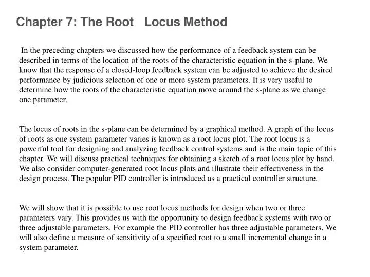
Chapter 7: The Root Locus Method In the preceding chapters we discussed how the performance of a feedback system can be described in terms of the location of the roots of the characteristic equation in the s-plane. We know that the response of a closed-loop feedback system can be adjusted to achieve the desired performance by judicious selection of one or more system parameters. It is very useful to determine how the roots of the characteristic equation move around the s-plane as we change one parameter. The locus of roots in the s-plane can be determined by a graphical method. A graph of the locus of roots as one system parameter varies is known as a root locus plot. The root locus is a powerful tool for designing and analyzing feedback control systems and is the main topic of this chapter. We will discuss practical techniques for obtaining a sketch of a root locus plot by hand. We also consider computer-generated root locus plots and illustrate their effectiveness in the design process. The popular PID controller is introduced as a practical controller structure. We will show that it is possible to use root locus methods for design when two or three parameters vary. This provides us with the opportunity to design feedback systems with two or three adjustable parameters. For example the PID controller has three adjustable parameters. We will also define a measure of sensitivity of a specified root to a small incremental change in a system parameter.
Graphical Method
Graphical Method
Root Locus Design GUI (rltool) The Root Locus Design GUI is an interactive graphical tool to design compensators using the root locus method. This GUI plots the locus of the closed-loop poles as a function of the compensator gains. You can use this GUI to add compensator poles and zeros and analyze how their location affects the root locus and various time and frequency domain responses. Click on the various controls on the GUI to see what they do.