Download
1 / 34
340 likes | 593 Views
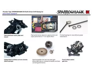
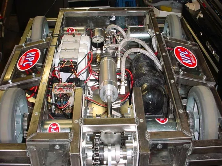
Motor mount from McMaster Carr. Gearboxes and motors from the “Team Nightmare” site. Material Selection. Light Strong Easy to fabricate Easy to integrate. Polycarbonate Sheets.

E N D
Material Selection • Light • Strong • Easy to fabricate • Easy to integrate
Polycarbonate Sheets Polycarbonate is a very tough thermoplastic material used in police riot shields, bulletproof windows, as armor and even structural material in combat robots. Polycarbonate plastic may also be found as the walls of the BattleBots arena (Lexan), as well as the high-strength walls of other robot arenas around the world. Polycarbonate used in robots have many advantages: 1. It is very lightweight compared to other material choices. About five to six times less dense than steel! 2. It is quite durable and has a tendancy to spring back into position when bent. It will not form to a bend as many metals will. 3. It is see-thru, making it a great choice for robot armor where you need to be able to see into the robot. 4. It does not conduct electricity and makes a great insulator for electrical systems. 5. Polycarbonate plastic is easy to work with. Cutting, drilling and even machining and tapping it is a breeze. You can find Polycarbonate plastic on many of the top robots in the sport of robotic combat.
COMPOSITE MATERIALS - CARBON FIBER "Composite" is a general term which means an assembly of dissimilar materials used together. They are carefully engineered and are uniquely suited to be extremely strong and surprisingly light weight. These materials consist of a resin matrix and a fiber reinforcement. As a result, Carbon Fiber is a fantastic material to use for robot armor, interior component mounting, and any situation where you want rigidity but do not want to add much weight. Carbon fiber is even lighter than Polycarbonate Plastic
Limit different sizes and types of threads of nuts and bolts
McMaster Carr has a large selection of spacers and standoffs
Attaching Wheels etc. • As the wheels get bigger your robot • Moves faster • May have more friction, therefore drawing more amperage • Will need more initial power to begin to make it turn
Multi-Purpose Hubs This is a great solution to hold various high-stress items that you'd like to spin, such as a sawblade. Depending on your particular application, this may also work quite nicely as a drive wheel hub. It is made especially for Robotic Combat standards of high quality, lightweight 6061 Aluminum on one of the finest of commercial lathes by some of the best makers in the USA. We chose 6061 Aluminum as the ideal material for this task at a reasonable price. It is much stronger than many of the other aluminum hubs you will find, with many times the shatter resistance of any kind of plastic hub. This hub comes with 6 black, 3/8" long, 1/4"-20 hex-socket head bolts to attach through the sawblade (or wheel) face and into the hub itself, so nuts should not be necessary.
Colson Bore Reducers from Team Nightmare site So you want to use one of the big Colson wheels with the large bore, but you don't want to use a monster shaft. This is what you need to reduce the large bore down to something more manageable. These are custom built 6061 Aluminum bore reducers that were made to fit the Colson Performa wheels. These reducers are made especially for Robotic Combat standards.
Couplers from McMaster Carr Couplings connect two shafts and transfer motion from one shaft to another. They attach via cap screws, set screws, a combination of keyways and set screws, or bushings. ANSI Keyways- Couplings with keyways give you a more secure hold and are especially good for alternating-motion applications. Keyways follow standard ANSI dimensions listed in the chart at right. Torque Ratings- Couplings are rated by the maximum torque they can carry, and sometimes by a limiting or maximum rpm. Maximum torque can be used to determine horsepower (or vice versa) by the following formula:
Pinhole Disk Couplers from McMaster Carr Also known as Schmidt couplings, these couplings handle three times more angular misalignment than the slotted-disc couplings above. Great for use with encoders, they allow zero backlash (they will not slip) and never need lubrication. For a complete coupling, you need to order two hubs and one disc from the same line in the listing below (for example, two 60635K1 hubs are designed to work with one 60635K86 disc). Hubs are aluminum and have an internal clamp-style collar with socket-head cap screw for a strong, nonmarring grip. Bore sizes smaller than 1/2" do not have keyways; 1/2" and larger have ANSI keyways. To Order: Please specify bore size from those available below. Note: You can use two hubs with different bore sizes in one coupling as long as the hub ODs are the same. Discs are Delrin. Temp. range is -30° to +150° F.
Acetal Helical Beam Couplings Three beams, or cuts, in these lightweight, corrosion resistant couplings provide flexibility for parallel and angular misalignment. Excellent for motion-control applications that require precise positioning for frequent starts and stops, they allow zero backlash (they will not slip) and never need lubrication. Couplings connect to shafts via integral shaft collars-no marring as with set-screw mounted couplings. Two socket-head cap screws are included. To Order: Where applicable, please specify bore size (A) and bore size (B) from those available below.For more information about couplings, see page 1029 . Note: You can choose any available bore size (A) and any available bore size (B) for a given hub OD.
About Gears In order to mesh, gears must have the same pitch (ratio of number of teeth to pitch dia.) and pressure angle (angle between contact points of meshing teeth). Pitch dia. is the dia. of the circle formed at the contact point of meshing teeth. Gears with 14 1/2° pressure angle are the original AGMA (American Gear Manufacturers' Association) standard. They provide smooth, quiet meshing and are good for replacements in existing designs. Gears with 20° pressure angle are the most recent AGMA standard, with stronger teeth and higher load capacities. If you need a gauge to help determine gear pitch and pressure angle, see 2069A on page 2048 . There are three types of gear pitch: Coarse (up to 20 pitch) for heavy duty power transmission; medium (20 to 64 pitch) for general purpose power transmission; and fine (more than 64 pitch) for light duty power transmission and instrumentation applications.
Helical gears Left hand helical Bevel gears Right hand helical Teeth are set at a 45° helix angle which, in parallel shaft applications, gives you more constant tooth contact for smoother, quieter operation and the ability to handle higher horsepower than comparable-size spur gears. Hubless design allows use in tight spots. Parallel-shaft applications require one right- and one left-hand gear. These gears can also be used with shafts at 90° angles; however, they are 50% less efficient due to reduced tooth contact area. Use gears with the same hand (two right-hand gears or two left-hand gears). All have a finished bore with keyway unless noted. To Order: Please specify right- or left-hand helix angle.
Timing belt gears Worm Gears Worm gears and worms produce a high speed-reduction ratio in a minimal amount of space. They're designed for use on shafts that intersect at a 90° angle. Worm gears are cast iron and have a plain bore (no set screws or keyway). Worms are steel and have a keyway and right-hand thread.Note: Speed-reduction ratio is determined by number of teeth. For example, a 20-tooth worm gear and its mating worm will give you a 20:1 ratio; a 30-tooth worm gear and its mating worm will give you a 30:1 ratio. Hubless spur gears Also called change gears, these gears feature a space-saving hubless design that makes it easier to mount two or more gears side-by-side. Gears have a finished bore with two keyways spaced 180° apart. You can attach gears to your shaft with a bushing, sold separately below. Bushings are steel, can be press-fit, and have two integral keys that match the hubless gear's keyways.
Sprockets In order for sprocket and chain to properly mesh, select a sprocket that matches your specific chain number and pitch. Pitchis the distance from one tooth valley to the next; this is where the centers of chain pins mesh with the sprocket. Finished Bore Steel Sprockets Bores are finished so these sprockets are ready to mount. They have a standard keyway, except 3/8" and 1/2" bore sizes. Keyways are on the centerline of tooth. All include two set screws. Use sprockets with ANSI single-strand chain. Made of steel. To Order: Please specify bore size. Standard bore sizes are: 3/8", 1/2", 5/8", 3/4" , 7/8", 1", 1 1/8", 1 3/16", 1 1/4", 1 3/8", 1 7/16" 1 1/2", 1 5/8", 1 3/4", 1 15/16", 2", 2 3/16", 2 7/16", and 2 15/16". Plain Bore Sprocket
Sprocket accessories Just like the plain bore sprockets, except these don't have a hub which makes them excellent for use in confined spaces. Sprockets do not include keyways or set screws. Use with ANSI single-strand chain. Minimum bore size is the furnished size; you can enlarge bore to the maximum bore size. Double strand plain bore sprocket Hubless plain bore sprocket Roller chain lubricator Double drive plain bore sprocket
Roller chain idler sprockets The bearings or bushings in these sprockets allow them to rotate freely while controlling chain slack to maintain proper tension and prevent whip. Steel sprockets have precision-cut teeth for longer chain life. Teeth on steel sprockets with plain bronze bearings and with needle bearings are also hardened to reduce sprocket wear. Steel sprockets with plain bronze bearings also have two plain washers and a hardened steel sleeve to protect the bearings. UHMW polyethylene sprockets are self-lubricating, flexible, and resistant to abrasion and impact.Bearing/Bushing Sprockets: Ball bearings are double-sealed and lubricated; bronze bearings/bushings are oil-impregnated; needle bearings have retainers separating the needle rollers to minimize internal friction and wear.
Chain & links Roller chain consists of alternating pin links (two pins supported by side plates) and roller links (two rollers on bushings, also supported by side plates). The pins (all of which are riveted, except where noted) pivot inside the bushings. The rollers are free-turning to provide rolling contact with sprocket teeth. Chain sizes are distinguished by pitch, the distance between pin centers. Some smaller-pitched roller chain is actually rollerless, and is constructed of pins and bushings only. Use roller chain and sprockets with the same ANSI No. Roller single link Offset single link Connecting link Connecting Link- A special pin link that's easily disassembled; use to join the ends of a length of chain to make a continuous strand and to splice lengths together. Roller Link- Add to chain to lengthen it. Note: Roller links for multistrand chain are single links placed side-by-side.Offset Link- A combination of a pin link and roller link. Standard chain has an even number of pitches; use an offset link to make a strand with an odd number of pitches.
Chain tools Use one tool to break and rivet roller chain. This tool can break ANSI 50 ( 3/8"- 5/8" pitch) and 60 ( 1/2"- 3/4" pitch) roller chain. Rivets #40-#60. You can bolt it to a workbench (using two 3/8"-24 bolts, not included), support it in a vise, or use it by hand (with included removable handle). Also includes rivet set, rivet anvil, and press plate. All attachments are made of 86L20 steel and are heat treated for strength and durability. Chain holders work like a third hand to help you insert and fasten connecting links. Just hook the jaws into each end of your chain and turn the handle on top (a knurled screw knob on Style A and a T-handle on Style B) until chain ends almost meet. Insert the connecting link and fasten. Made of carbon steel.
Roller chain tensioner These tensioners ride on chain, compressing it axially to control tension. They don't need to be mounted to a structure. They require no tools, lubrication, idler sprockets, or bearings. Saddle blocks ride on chain midway between the drive sprocket and driven sprocket and are joined by adjustable straps which take up the slack. Tensioners are made of UHMW polyethylene (FDA and USDA compliant for food contact) with stainless steel housing and zinc-plated steel screws and wing nuts. Max. temp. is 200° F. Tension force not rated.
Steel semi precision ball bearings The unground inner raceways in these bearings give you good performance at moderate speeds and loads. Inner and outer sleeves are hardened carbon steel. Temperature range is -20° to +250° F.Standard Bearings- Tolerance for open bearings: +.005" to -0" for shaft dia., +0" to -.005" for OD, and ±.010" for width. For double- shielded and double-sealed bearings: +.005" to -0" for shaft dia., +0" to -.0005" for OD, and ±.005" for width.Flanged Bearings- Allow precise positioning during installation, so you don't need snap rings or to counterbore the housing. Tolerance: +.005" to -0" for shaft dia.; +.005" to -0" for OD, and ±.010" for width on open bearings; ±.005" for width on double-sealed.
Radial load track rollers Also known as cam followers, track rollers guide linear motion in a variety of machine tool and material handling applications. In addition, they resist shock loads.Radial-Load Track Rollers- Support loads perpendicular to their axis of rotation. They usually contain needle roller bearings, cylindrical roller bearings, or sleeve bearings. Needle roller bearings offer higher load carrying capacity than sleeve bearings. Cylindrical roller bearings also offer high load carrying capacity, as well as the ability to run at higher speeds without forcing the roller out of alignment. Sleeve bearings have no rolling element-loads are supported through sliding motion between two low-friction surfaces. Sleeve bearings are designed for light loads and low speeds. Some radial-load rollers have a hex-socket head or a slotted head for ease of fastening.