Download
1 / 42
420 likes | 428 Views
Research at Geophysical and Multiphase Flow Laboratory. Sridhar Balasubramanian. Department of Mechanical Engineering Indian Institute of Technology, Bombay. Geophysical & Multiphase Flow-I. Plume dynamics in buoyant environment Hot exhaust from chimney Volcanic eruptions

E N D
Research at Geophysical and Multiphase Flow Laboratory Sridhar Balasubramanian Department of Mechanical Engineering Indian Institute of Technology, Bombay
Geophysical & Multiphase Flow-I • Plume dynamics in buoyant environment • Hot exhaust from chimney • Volcanic eruptions • Cloud dynamics • Effluent discharge into sea/rivers • Research questions surrounding this topic. • Evolution, growth and spread is not well understood • Plume entrainment dynamics – Is it self similar? • Presence of mean flow/current on the plume behavior? (i.e. wind speed and direction) • Presence of dilute particle concentrations on plume? (i.e. particulates, bubbles etc.)
Fluid dynamics of plumes • Plume develops differently for with particle and without particle case. • Noticeable difference at time t=90s t=10s t=40s t=90s No Particles in the plume Plume w/ heavy particles (100 m)
Fluid dynamics of plumes • Particle laden plume propagates slowly • Peeling of the plume is seen with particles. No Particles in the plume Plume w/ heavy particles (100 m) Rf is the plume propagation plotted as a function of time (t). Peel off
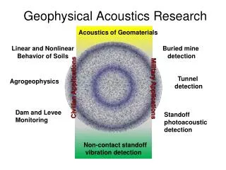
Geophysical & Multiphase Flow-II • Turbulent convection and heat transport in the presence of rotation • Atmospheric large scale circulation • Ocean circulation • Cyclones and thunderstorms • Polar vortex • Heat transfer in earth’s inner core • Research questions surrounding this topic • Effect of low rotation rate on circulation dynamics (mimicking near equatorial regime) • Effect of high rotation rate on circulation dynamics (mimicking near mid-latitude/polar region) • Geostrophic turbulence and dynamics of heat transfer
Rotating turbulent convection Low rotation • Rotating tank set up and dye visualization. High rotation
Geophysical & Multiphase Flow-III • Flow dynamics & turbulence modulation in dispersed particle laden flows • Dusty gas flows in environment • Sediment transport in ocean • Biomechanical process (blood flow) • Droplet dynamics in clouds • Industrial processes (fluidized bed combustion) • Research questions surrounding this topic. • Particle volume concentration less than v=1% • Turbulence attenuation or turbulence augmentation? • Wake dynamics and particle vortex shedding in presence of low particle concentration in a fluid flow? • Effect of particle clustering on fluid flow and mixing? • Flow regimes in which sediment suspension, settling and re-suspension occurs? Image showing Particle clustering
Dynamics of particle-laden flows Water channel to study turbulence in particle-laden channel flow Dye visualization showing turbulence modulation in particle-laden flow
Geophysical & Multiphase Flow-IV • Flow dynamics of superheated jets • Aero- and auto- combustors • Nuclear reactors • Spray atomization • Fuel injection in automobiles • High pressure industrial processes • Research questions surrounding this topic. • Break up mechanism of the high temperature jet? • Droplet spectra and size distribution? • Understanding Aerodynamic/shear instability • Understanding Flashing mechanism. • Different types of instability regimes (ligament, helical, shear, and axisymmetric) Break up of a superheated jet
Dynamics of superheated jet Break down of ligament t1 3 ms Shear instability t2 5.5 ms (from t1) Helical pattern t3 7 ms (from t2) Axisymmetric structure t4 7.5 ms (from t3) Beginning of Flashing? t5 8 ms (from t4) Note: t1= t0+tdevelop;t00 s
Research at IC Engine and Combustion Laboratory Arindrajit Chowdhury Department of Mechanical Engineering Indian Institute of Technology, Bombay
Droplet Combustion Studies • Objectives • Hi-speed videography showing droplet and flame behavior • Evaluation of droplet burning rate • Measurement of the flame dimension variation with time • Study of the flame structure • Variation of burning rate constant with initial droplet diameter • Effects of natural convection, fiber conduction, and ambient O2% 1 2 3 • Optical windows • Bottom flange • Electrodes 4 6 NM flame IPN flame 5 • Quartz rod • Top flange • Window flange
Droplet Combustion Studies k vs. D0 for Pure IPN droplets k vs. D0 for Pure NM droplets
Exhaust Pure IPN Strand Studies Pressure Sensor • Objectives • Combustion of liquid strands at various ambient pressures • Evaluation of linear burning rate of liquid propellants • Effect of variation of strand diameter on linear burning rate • Theoretical estimation of the burning rates using pool fire analogy • Study of the flame structure Pressure relief valve To PC Data Acquisition System Camera Thermocouples Ignition Source 0 sec 2 sec 4 sec 6 sec Regulator R Pure IPN strand at atmospheric pressure R Needle valve Strand combustion setup air
Pure IPN Strand Studies Bipropellant Flame Monopropellant Flame Bipropellant Model Monopropellant Model H H S Ll Ll thk thk di di La=20 mm La=20 mm Fuel Fuel do do Comparison of experimental and theoretical results
Spray Combustion Study • Objectives • Constant volume spray combustion of IPN • Chamber pressure varied from 1 to 7 bar • Φ variation from 0.5 to 0.08 • Rise in chamber pressure recorded • Visual study conducted at 3000 fps • FTIR spectroscopy of exhaust phenomenological model proposed Experimental Setup Visualization Study (step ≈ 4 ms)
Research at Thermal Hydraulics Test Facility Lab. Prof. Kannan Iyer Department of Mechanical Engineering Indian Institute of Technology, Bombay
Experimental Studies on Critical Heat Flux in 54 Rod Bundle Cluster
Critical Heat Flux in 54 Rod Bundle Cluster • Critical Heat Flux (CHF) It is the heat flux at which boiling crisis takes place followed by abrupt rise in surface temperature. This can lead to rupture and burnout of heater surface. • Research Motivation • Advanced Heavy Water Reactor (AHWR) has a natural circulation system as a main heat transport system; The core of each channel is cluster of 54 Fuel Rods. • Flow instabilities/Power excursion could result in burn out scenario. • The complex mechanism of two phase heat transfer in the core call for investigations of CHF for each specific design of reactor. • Experimental studies are considered more trustworthy to understand boiling crisis phenomenon at CHF. • Characterization of CHF puts an upper bound on operating power 54 Rod Bundle of the reactor. Cluster
Salient Features of Facilities • D.C. Power Source • Maximum Available Power = 650 kW • Different voltage and current combinations for different length of heaters. • Data Acquisition System • Distributed data collection system with 5 data modules. • Fastest Data collection rate @0.5 sec. • Inbuilt Alarm and Relay facilities to safeguard plant. • Primary Loop • 54 Rod Bundle Cluster indirectly heated by D.C. current. • Use of fluid to fluid scaling philosophy. (FC-84) in place of water as working fluid. • Canned pump to recirculate fluid through primary loop. • Compact condenser to work as heat sink. • Motorised control valve,DPT,PT for smart and accurate control.
Secondary Loop V1 H X Hot Fluid Out V6 Vapor Flow Cold water In Third Floor Bypass Main flow Separator Bypass Condensate Flow vacuum P Cooling Tower Separator Secondary Pump Riser Second Floor C-Expansion Loop Post heated zone Downcomer First Floor Rod Bundle Heater Zone Preheater Storage Tank venturimeter C.V. Primary pump Ground Floor FLOWSHEET OF EXPERIMENTAL SET UP FOR CHF STUDIES IN FRCS
Dryout Situation for Water Equivalent Conditions of 64 bar For 64 bar water equivalent pressure i.e. 3.8 bar for FC-84, dryout situation occurs while inching the power in the reactor to 95 kW. Dryout is accompanied by flow oscillations triggered by oscillations in system pressure
Research at Fluid Mechanics and Fluid Power Lab Prof. S.V.Prabhu Department of Mechanical Engineering Indian Institute of Technology, Bombay
Areas of Research • Fire dynamics • Flowmetering • Wind Turbines and Hydrokinetic turbines • Jet impingement (air jets and flame jets) • Two phase flow and heat transfer • Melting and solidification • Spray dynamics
Open Pool Fires D = 1.0 m
Two Phase Flow and Heat Transfer Appearance of red hot spot Red hot spreads Critical heat flux
Melting and Solidification of lead Asbestos Bakelite 6 4 5 Air gap 94 45 Lead 4 6 Heater Thermocouple Mica 60 14 14 2 6 6 Electric Wire 55 mm Mica Sheet Nichrome Strip 55mmm Nichrome Strip behind the sheet 10 mm
Research at Optical Instrumentation Lab Atul Srivastava Department of Mechanical Engineering Indian Institute of Technology, Bombay
Non-Intrusive Techniques: Mach-Zehnder Interferometer and Color Schlieren Combustion flame experiments Vertical flat plate experiments Thermal Boundary layer of heated horizontal plate in mini channel
Non-Intrusive Techniques: Mach-Zehnder Interferometer and Color Schlieren Double Diffusive Convection Convection Regime Diffusion Regime Sodium Chlorate solution at 4% super saturation Sodium Chlorate solution at 2% super saturation Dual wavelength interferogram Crystal growth experiments
Rayleigh Benard experiment with dilute Al2O3 nanofluid Diffusion of heat in 0.005% conc. of nanofluid ΔT = 10C ΔT = 1.40C Comparison of thermal boundary layer of distilled water and 0.02% conc. of nanofluid ΔT = 2.30C ΔT = 1.80C Variation of convective flow field for 0.03% conc. of nanofluid
Research at Steam Power Lab R.P. Vedula Department of Mechanical Engineering Indian Institute of Technology, Bombay
Steam Lab. (RPV-1) • Experimental heat transfer research is one of the activities in the Steam Power Laboratory. • The work going on includes measurements related to: • Film and Impingement cooling • Heat transfer enhancement using passive inserts • Supercritical pressure and temperature heat transfer • One example is discussed in the next slides. Others can be seen during the lab. visits
Steam Lab. (RPV-2) • Turbine Blades are often cooled to keep temperatures within permissible limits • One configuration is where a channel converges from one end to another. Ribs are placed within the channel to enhance heat transfer coefficients • Measurements indicate the nature of heat transfer coefficients within the channel and the most appropriate configuration to use.
Steam Lab.(RPV-3) • Test section wall with different ribs is shown below. Secondary flows cause local flow disturbances and heat transfer coefficients to vary. Wall is heated and forms part of a channel through which air flows. Top Line Bottom Line Bottom Apex Line Center Line Top Apex Line W Rib with Central Apex Downstream (WCAD) V Rib with Central Apex Downstream (VCAD) W Rib with Central Apex Upstream (WCAU) V Rib with Central Apex Upstream (VCAU) Straight Rib
Steam Lab.(RPV-4) • Significant increase in coefficients of heat transfer due to the ribs can be noticed • Contour plot of Nusselt number distribution indicating the direction of cross flows due to ribs
Steam Lab.(RPV-5) • Any heat transfer enhancement device will provide additional pressure drop. Friction factors are very high. • One way to quantify the ‘goodness’ of the device is the enhancement at constant pumping power as a function of smooth tube equivalent Reynolds no.