Download

1 / 21
210 likes | 217 Views
Beam Test Results on Deep NWell MAPS Matrix. S. Bettarini University & INFN, Pisa on behalf of the SLIM5 Collaboration and the SVT-SuperB group. SuperB meeting – Orsay 15-18 Feb. 2009. Outline. Deep NWell M onolithic A ctive P ixel S ensor design concept Caracterization of apsel4D

E N D
Beam Test Results on Deep NWell MAPS Matrix S. Bettarini University & INFN, Pisa on behalf of the SLIM5 Collaboration and the SVT-SuperB group SuperB meeting – Orsay 15-18 Feb. 2009
Outline • Deep NWell Monolithic Active Pixel Sensor design concept • Caracterization of apsel4D • Test-beam setup • Alignment procedure /Track fit • Results on DUT= MAPS : • Efficiency vs. threshold • Efficiency inside the pixel cell • (Intrinsic) Resolution • Improvements on the design of the cell • Conclusions
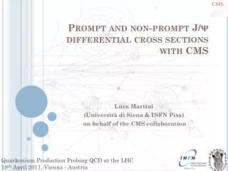
Pixel structure compatible with data sparsification architecture Deep NWell MAPS design PRE SHAPER DISC LATCH competitive nwell Deep nwell • CMOS MAPS for future vertex detectors: thin (<50 um) but also need to be fast (background rate @ SuperB several MHz/cm2) • New approach in MAPS design: hybrid-pixel-like structure to improve the readout speed: the APSEL chip series • Full in-pixel signal processing chainexploiting triple well CMOS process • Deep NWell as collecting electrode with most of the front-end overalapped in the pwell • Can extend collecting electrode (charge preamp --> gain independent of sensor cap. ) • Allow design with small “competitive” nwells for PMOS inside the pixel. Area kept to a minimum:, they steel signal to the main DNW electrode. • Fill factor = DNW/total n-well area ~90% in current design SLIM5 Collaboration - INFN & Italian University 50x50mm2 pixel
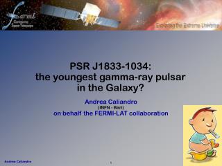
Latest chips APSEL 90Sr electrons APSEL3T1 M2 S/N=23 Landau mV Cluster signal (mV) Noise events properly normalized APSEL3 • Pixel cell optimization (50x50 mm2) • Increase S/N (15-30) • Power dissipation:30 mW/ch • <Signal> for MIP (MPV) = 1000e- • ENC ranging from 30 to 60 e- in the different front-end versions APSEL4D • First MAPS matrix with in-pixel sparsification and timestamp info on hit. • 4Kpixel matrix with data driven readout architecture LV1 trigger system with tracks info based on Associative Memories • Pixel cell & matrix implemented with full custom design and layout • Perifery readout logic synthetized in std-cell from VHDL model APSEL4D sub 11/2007- rec 3/2008 32x128 4k pixel matrix for beam test
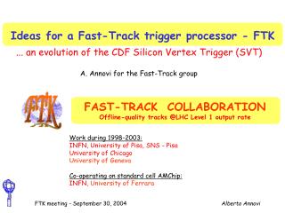
32x128 pix - 50 mm pitch perif & spars logic MP 4x4 pixels Data lines in common 2 MP private lines Column enable lines in common Periphery readout logic Data out bus APSEL4D:4096 pixel matrix with data driven sparsified readout + timestamp Implemented architecture needs to minimize: • In-pixel PMOS (competitive nwells) to preserve the collection efficiency. • digital lines for point to point connections to allow scalability to large matrix and to reduce possible cross talk with the sensor underneath. Periphery readout logic: • Register hit MP & store timestamp • Enable MP readout • Receive, sparsify, format data to output bus • Matrix subdivided in MacroPixel (MP=4x4pixels) with point to point connection to the periphery readout logic Readout tests • All readout functionality tested with a dummy matrix implemented on chip. • The readout is working properly even with 100% occupancy. • Three clocks are used: the BCO clock, used for the timestamp counter, a faster readout clock, and a slow control clock. • Test performed with RDCLK up to 50 MHz
APSEL4D Lab. Results Offset distribution Threshold dispersion 8 mV Average Noise 10.5 mV Gain distribution (all pixels in matrix) mV 55Fe 5.9 keV peak (all pixels in matrix) Gain = 890 mV/fC Spread = 6% Noise distribution 1390 THRDAC = 230mV mV/fC THR(DAC) mV • Noise and threshold from threshold scans • <Threshold dispersion> inside matrix: 8mV (57e-) • <pixel noise>: 10.5 mV (ENC = 75e-) with 20% dispersion inside the matrix • Gain Calibration (55Fe-5.9 keV peak) • <Gain> = 890 mV/fC ± 6% • Obtained by differentiating the integral spectrum since no analog info available. • Cross talk effects observed in APSEL4D, correlated with the readout activity, still under investigation. A new version of the chip submitted in Nov ‘08 with more diagnostic features and modifications to reduce some potential source of digital crosstalk. • Effects reduced by lowering the digital voltage from 1.2 to 1 V (still able to operate the matrix and the readout).
SLIM5 Beam test SLIM5 Beam test 3-16 Sep. 2008 @ PS-CERN (12 GeV/c protons) Main goals: • APSEL4D DNW MAPS matrix resolution & efficiency measurements • Thin (200 mm) striplets module with FSSR2 readout chips • First demostration of Level1 capability with silicon tracker information to Associative Memories
Experimental set-up APSEL4D chip 10 mm2 active area APSEL4D chip Some numbers: • Maps readout clock 20 MHz • DAQ rate 30 kHz • 90 M events on disk (40 Gb)
Alignment procedure • Select events with 1! candidate track. • Residual evaluated for every track passing through the detector’s active area. • Residual is a function of: • translation parameters Δx, Δy • rotation angles around z (φ), y(ϑ), x(γ) axes: Resi = Resi (φ,ϑ,γ,Δx,Δy) i= detector index • Alignment parameters extracted by minimizing the residuals. • Iterate: re-position the detectors, re-evaluate the residuals until convergence. • Alignment procedure validated on MC. • After alignment, residuals for strip, MAPS detectors: ~1 μm (transl), 1/10 degree (rotation) • Small systematic errors on data could be present: noise hits, uncertainty on z position of detectors… . Align detectors within few μm is fine for our purposes.
Pattern Recognition / Trk Fit • Used a very simple algorithm : start from combining SpacePoint (U hit + V hit) on L0, L3 (outer telescope dets) to generate a pseudo track. • Add hits on the inner telescope detectors (L1, L2) if distance from pseudo track is within a fiducial road width, typically 0.1-0.2 cm before alignment and 0.05 cm after alignment. • Rejected events with number of hits per side greater than 5 on telescope detectors (to reduce combinatory). • Track fit: Least Square Method to extract track parameters. Kalman Filter not used. Multiple scattering not accounted in track fit. • Prob(χ2) is flat when assigning 10 μm error for SpacePoints (SP). The estimated error changes in different sets of runs with different alignment. • The estimated uncertainty (due to fit) on track intercept on DUT is 5 μm (evaluated using track fit covariance matrix). As a rule of thumb we expect 10 μm/sqrt(#SP). Prob(χ2)>10%
Effect of the multiple scattering on DUT Fit track Real track { Residual MC: σ=6μm
MAPS efficiency • Number of tracks intersecting DUT • Number of clusters associated to tracks evaluated by the Residual plots: • Res = SpacePointmeas- SpacePointtrk • Fit: Gaussian(signal) + line(noise) • Clusters associated to tracks = Gaussian’s area • Efficiency = #clusters/#tracks
DNW MAPS Hit Efficiency vs threshold ½ MIP • MAPS hit efficiency up to 90 % with threshold @ 450 e- (~ 4s_noise + 2s_thr_disp) • 300 (chip23) and 100 (chip22) mm thick chips give similar results • Observed uniform efficiency across the area of the whole matrix. The competitive Nwells in pixel cell steel charge, reducing the hit efficiency: • Fill factor DNW area /total Nwell area ~ 90 % in present design
Chip 22: point@lowest threshold read out sweep Efficiency varies vs: • the matrix columns • run time Hints of a readout problem. (min)
Efficiency inside the pixel cell Real Track Fit Track Meas SP ΔU The residual on the extrapolated impact point of the track ~ 15 um. The 50 um cell is divided into 3x3 regions. Track uncertainty dilutes raw efficiency: • Cross feed among cells unfolded. Efficiency in the pixel cell (data) correlated with layout. As expected: • Highest efficiency in the region of collecting electrode • Lower efficiency due to competitive nwells Competitive nwells Efficiency inside pixel cell (cross-feed unfolded) DNW sensor mm
MAPS Resolution • From the width of residual plot extract intrisic resolution according to: • Results consistent with 50 mm pitch with digital readout (50/sqrt(12) = 14.4 mm) MAPS Intrinsic Resolution vs Threshold Y res < X res: correlation with efficiency inside the cell. x Coordinate y Coordinate Low stat. runs
Cell Design Improvements • Room for efficiency improvements with a different design of the sensor (multiple collecting electrodes around competitive nwells) • Fast device simulation developed for cell optimization • ionization, charge diffusion, front-end response included • good agreement simulation vs efficiency data • Already submitted chip apsel5T: • 2 design options [effi(@400e-)~98%] • 40x40 um pitch • No-shaper routing possible for a matrix 128x128 pixels
Conclusions • A first MAPS matrix with in-pixel sparsification and timestamp information for hits fully characterized and tested with beams with very encouraging results: • Threshold dispersion across matrix ~ 60 e- • Pixel Noise ENC = 75 e- • Hit efficiency up to 92% (sensor design not optimized yet!) with good uniformity across the matrix. • Intrisinc resolution ~ 14 mm compatible with 50 mm pitch and digital readout. • Already submitted a new chip with improved cell design. Ready to be tested with beam next summer.
SLIM5-Silicon detectors with Low Interactions with Material G. Batignani1,2, S. Bettarini1,2, F. Bosi1,2, G. Calderini1,2,, R. Cenci1,2, A. Cervelli1,2, F. Crescioli1,2, M. Dell’Orso1,2, F. Forti1,2, P.Giannetti1,2 , M. A. Giorgi1,2, A. Lusiani2,3, G. Marchiori1,2, M. Massa1,2, F. Morsani1,2, N. Neri1,2, E. Paoloni1,2, M. Piendibene1,2, G. Rizzo1,2 , L.Sartori1,2, J. Walsh2 C. Andreoli4,5, E. Pozzati4,5,L. Ratti4,5, V. Speziali4,5, M. Manghisoni5,6, V. Re5,6, G. Traversi5,6, L.Gaioni4,5 M. Bomben7, L. Bosisio7, P. Cristaudo7, G. Giacomini7, L. Lanceri7, I. Rachevskaia7, L. Vitale7, M. Bruschi8, R. Di Sipio8, B. Giacobbe8,A. Gabrielli8, F.Giorgi8, C. Sbarra8, N. Semprini8, R. Spighi8, S. Valentinetti8, M. Villa8, A. Zoccoli8, D. Gamba9, G. Giraudo9, P. Mereu9, G.F. Dalla Betta10 , G. Soncini10 , G. Fontana10 , L. Pancheri10 , G. Verzellesi11 1Università degli Studi di Pisa, 2INFN Pisa, 3Scuola Normale Superiore di Pisa, 4Università degli Studi di Pavia, 5INFN Pavia, 6Università degli Studi di Bergamo, 7INFN Trieste and Università degli Studi di Trieste 8INFN Bologna and Università degli Studi di Bologna 9INFN Torino and Università degli Studi di Torino 10Università degli Studi di Trento and INFN Padova 11Università degli Studi di Modena e Reggio Emilia and INFN Padova