Download
1 / 45
1.41k likes | 3.24k Views
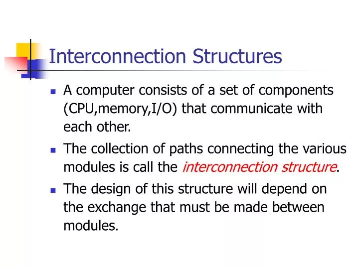
Interconnection Structures. A computer consists of a set of components (CPU,memory,I/O) that communicate with each other. The collection of paths connecting the various modules is call the interconnection structure .

E N D
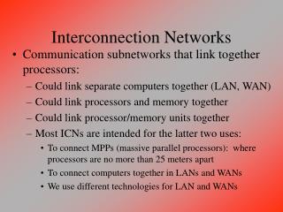
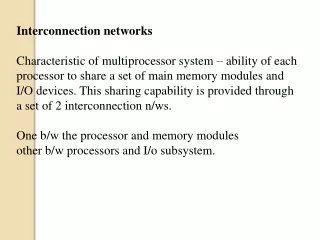
Interconnection Structures • A computer consists of a set of components (CPU,memory,I/O) that communicate with each other. • The collection of paths connecting the various modules is call the interconnection structure. • The design of this structure will depend on the exchange that must be made between modules.
Read Read Write Memory N Word 0 . . . N-1 I/O Module M Ports Write Internal Data Data Address Address External Data Data Internal Data Interrupt Signal External Data CPU Instructions Data Interrupt Signal Control Signal Data Input/Output for each module
Type of transfers • Memory to CPU • CPU to Memory • I/O to CPU • CPU to I/O • I/O to or from Memory (DMA)
Bus Interconnection • A bus is a communication pathway connecting two or more device. • A key characteristic of a bus is that it is a shared transmission medium. • A bus consists of multiple pathways or lines. • Each line is capable of transmitting signal representing binary digit (1 or 0)
Bus Interconnection • A sequence of bits can be transmit across a single line. • Several lines can be used to transmit bits simultaneously (in parallel). • A bus that connects major components (CPU,Memory,I/O) is called System Bus. • The most common computer interconnection structures are based on the use of one or more system buses.
Bus Structure • A system bus consists of 50-100 lines. • Each line is assigned a particular meaning or function. • On any bus the lines can be classified into 3 groups • Data lines • Address lines • Control lines
Data Lines • Provide a path for moving data between system modules. • These lines, collectively, are called the data bus • The data bus typically consists of 8,16 or 32 separate lines, the numbers of lines being transferred to as the width of the data bus. • Each line carry only 1 bit at a time, the number of lines determines how many bits can transferred at a time - overall system performance.
The Address Lines • Used to designate the source or destination of the data on the data bus • The width of the address bus determines the maximum possible memory capacity of the system.
Used to control the access to and the use of the data and address lines. Typical control lines include Memory write Memory read I/O write I/O read Clock Reset Bus request Bus grant Interrupt request Interrupt ACK Transfer ACK The Control Lines
The operation of the bus If one module wishes to send data • obtain the use of the bus • transfer data via the bus If one module wishes to request data • obtain the use of the bus • transfer request to the other module over the control and address lines, then wait for that second module to send the data.
Physical Bus Architecture • System bus is a number of parallel electrical conductors. • The conductors are metal lines etched in a card or printed circuit board. • The bus extends across all of the components tat taps into the bus lines.
Multiple-Bus Hierarchies • More devices attached to bus, propagation delays affect performance • How to arbitration? • Bottleneck as the aggregate data transfer demand approaches capacity of bus. (e.g graphics & video controller) • How to increase bus?
Traditional Bus Architecture • Local bus • CPU - Cache • System bus • Main memory - Cache • Expansion bus • I/O Modules - Main memory
High-Performance Architecture • Local bus • CPU - Cache/bridge • System bus • Cache/bridge - memory • High-speed bus • High-speed I/O module - Cache/bridge • Expansion bus • Low-speed I/O modules - Expansion interface
Bus Design • Method of Arbitration • Centralized • Distributed • Data Transfer Type • Read • Write • Read-modify-write • Read-after-write • Block • Type • Dedicated • Multiplexed • Bus Width • Address • Data • Timing • Synchronous • Asynchronous
Type • Dedicated permanent assigned bus either to one function or to a physical subset of computer components • Multiplexeduse in the same bus for multiple purpose (Time Multiplexing)
Bus Width • Address the wider of address bus has an impact on range of locations that can be referenced • Data the wider of data bus has an impact on the number of bits transferred at one time
Synchronous occurrence of events on the bus is determined by a clock (Clock Cycle or Bus Cycle) which includes line upon Asynchronous occurrence of one event follows and depends on the previous event. Timing
Centralized bus controller (Arbiter), hardware device,is responsible for allocating time on the bus (daisy chain) Distributed access control logic in each module act together to share bus Method of Arbitration
Data Transfer Type • Read Multiplexedbus is used to specifying address and then for transferring data after a wait while data is being fetched • Read Dedicatedaddress is put on bus and remain there while data are put on the data bus
Data Transfer Type • Write Multiplexedbus is used to specifying address and then transferring data (same as read operation) • Write Dedicateddata put on data bus as soon as the address has stabilized
Data Transfer Type • Read-modify-write address is broadcast once at beginning a simply read is followed immediately by a write to the same address • Read-after-write a write followed immediately by a read from the same address,performed for checking purposes
Data Transfer Type • Block one address cycle is followed by n data cycles. The first data item is transferred to or from the specified address; remainder data items are transferred to or from subsequent addresses
Samples of Bus • ISA (Industry Standard Architecture) • MCA (Micro Channel Architecture) • EISA (Extended ISA) • VL Bus (VESA Local Bus) • PCI Bus (Peripheral Connection Interface)
Industry Standard Architecture • ISA is a standard bus (computer interconnection) architecture that is associated with the IBM AT motherboard. • It allows 16 bits at a time to flow between the motherboard circuitry and an expansion slot card and its associated device(s).
Micro Channel Architecture • Developed by IBM for its line of PS/2 desktop computers, MCA is an interface between a computer (or multiple computers) and its expansion cards and their associated devices. • MCA was a distinct break from previous bus architectures such as ISA. • The pin connections in MCA are smaller than other bus interfaces. For this and other reasons, MCA does not support other bus architectures.
Micro Channel Architecture (cont.) • Although MCA offers a number of improvements over other bus architectures, its proprietary, nonstandard aspects did not encourage other manufacturers to adopt it. • It has influenced other bus designs and it is still in use in PS/2s and in some minicomputer systems.
Extended Industry Standard Architecture • EISA is a standard bus architecture that extends the ISA standard to a 32-bit interface. It was developed in part as an open alternative to the proprietary Micro Channel Architecture (MCA) that IBM introduced in its PS/2 computers. • EISA data transfer can reach a peak of 33 megabytes per second
VESA Local Bus • VESA VL bus is a standard interface between your computer and its expansion slot that provides faster data flow between the devices controlled by the expansion cards and your computer's microprocessor. • A "local bus" is a physical path on which data flows at almost the speed of the microprocessor, increasing total system performance.
VESA Local Bus (cont.) • VESA Local Bus is particularly effective in systems with advanced video cards and supports 32-bit data flow at 50 MHz • A VESA Local Bus is implemented by adding a supplemental slot and card that aligns with and augments an ISA expansion card. (ISA is the most common expansion slot in today's computers.)
Peripheral Component Interconnect • PCI is an interconnection system between a microprocessor and attached devices in which expansion slot are spaced closely for high speed operation. • Using PCI, a computer can support both new PCI cards while continuing to support ISA expansion cards, currently the most common kind of expansion card.
Peripheral Component Interconnect (cont.) • Designed by Intel, the original PCI was similar to the VESA Local Bus. • PCI2.0 is no longer a local bus and is designed to be independent of microprocessor design. • PCI is designed to be synchronized with the clock speed of the microprocessor, in the range of 33 to 66 MHz. • Standard : Up to 64 data-lines at 66 MHz. Raw transfer rate of 528 MBps or 4.224 Gbps.
Peripheral Component Interconnect (cont.) • PCI is now installed on most new desktop computers, not only those based on Intel's Pentium processor but also those based on the PowerPC. • PCI transmits 32 bits at a time in a 124-pin connection (the extra pins are for power supply and grounding) and 64 bits in a 188-pin connection in an expanded implementation.
Peripheral Component Interconnect (cont.) • PCI uses all active paths to transmit both address and data signals, sending the address on one clock cycle and data on the next. • PCI deliver better system performance for high-speed I/O subsystems e.g. graphic display adapters, network interface controllers, disk controllers
PCI A Single-processor System A Multiprocessor System
Port Serial Parallel PS/2 PCMCIA USB (Universal Serial Bus) No port Infrared Bluetooth Interface
Universal Serial Bus • Standard bus which is invented by a group of companies : Compaq, DEC, IBM, Intel, Microsoft, NEC, Northern Telecom, etc. • Not change switch, jumper on board or other devices • Can use the same cable • Device that use USB can use power supply from PC. • Up to 127 devices connected off single port • Support real-time system • Hot Plug-in • Low cost
Accelerated Graphics Port • AGP is an interface specification that enables 3-D graphics to display quickly on ordinary PC. • AGP is an interface designed to convey 3-D images (ex:-from Web sites or CD-ROMs) much more quickly and smoothly than is possible today on any computer other than an expensive graphics workstation. • The interface uses your computer's main storage (RAM) for refreshing the monitor image and to support the texture mapping, z-buffering, andalpha blending required for 3-D image display.
Accelerated Graphics Port (cont.) • The AGP main memory use is dynamic, meaning that when not being used for accelerated graphics, main memory is restored for use by the operating system or other applications. • Intel, which has taken the lead in developing its specifications, introduced AGP into a chipset for its Pentium microprocessor. • The newer, faster microchips in Pentium line are designed to work with the AGP chipset. Intel says the advanced floating point unit and faster cache algorithm of the more advanced Pentiums are better adapted for 3-dimensional applications.