Download
1 / 16
160 likes | 249 Views
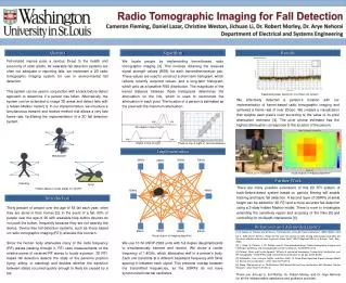
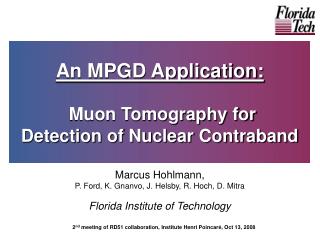
Tomographic Imaging of nuclear contraband using a cubic foot muon-tomography station. J. Twigger , V. Bhopatkar, E. Hansen, M. Hohlmann, J.B. Locke, M. Staib. Florida Institute of Technology High Energy Physic Lab A. Reconstruction Design Physics of a Gaseous Electron Multiplying Detector

E N D
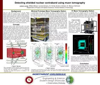
Tomographic Imaging of nuclear contraband using a cubic foot muon-tomography station J. Twigger, V. Bhopatkar, E. Hansen, M. Hohlmann, J.B. Locke, M. Staib Florida Institute of Technology High Energy Physic Lab A
Reconstruction • Design • Physics of a Gaseous Electron Multiplying Detector • Purpose • Visual Representation of Muon Scattering • Presenting Multiple Images on the Discrimination of Materials with Different Atomic Numbers (Z) and Density • Current plans for Improvement • The near future Overview
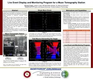
The ultimate goal of reconstruction is to find the Point of Closest Approach (POCA) and corresponding scattering angle. • Using an incoming and outgoing track we are able to calculate the amount of scattering a muon experiences while travelling through dense materials. • This scattering is small, requiring extremely accurate spatial resolution from the detectors. Reconstruction
POCA Reconstruction Scattering Angle Point of Closest Approach . θ1
The Muon Tomography Station Incoming muon track Active Volume Scattering Outgoing muon track
A View from the Outside Each readout panel contains 768 readout strips in X and Y plane 30 cm x 30 cm triple-GEM detectors +y +x
Exploded View of the GEM Detector Drift Region Each GEM is filled with an Argon/Carbon Dioxide mixture during operation GEM foil 1 Spacer Frame
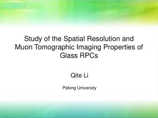
Differentiating Materials Lead: 82 Z Density: 11.34 g/cm3 Tungsten: 74 Z Density: 19.25 g/cm3 Uranium: 92 Z Density: 19.1 g/cm3 Tin: 50 Z Density: 7.31 g/cm3 Iron: 26 Z Density: 7.87 g/cm3
Discrimination and Shielding The Brass Shield Top-View Uranium Target at the Middle
Identifiable Shielding Outer Shielding Small Gap
The Lead Shielded Target Inside sit four different blocks, including a large cube of depleted uranium.
The amount of scattering is proportional to the atomic number and density of the material. Allowing for the imaging of material that is surrounded by commonly used metals like Iron or Steel. • The ability to image such dense materials as uranium will provide a more effective way of detecting illegal nuclear material. In Summary
Experimenting with new Detector Geometries and Designs • Live Display of targets in the MTS Station • Experimenting with new readout structures on the miniature GEM detectors The Near Future