Download
1 / 13
140 likes | 1.09k Views
Introduction. Block diagramsConvenient tool to represent closed-loop systemsAlso used to represent control systems in SimulinkClosed-loop transfer functionsTransfer function between any two signals in a closed-loop systemUsually involve setpoint or disturbance as the closed-loop input and the c

E N D
1. Closed-Loop Transfer Functions Introduction
Stirred tank heating system
Closed-loop block diagrams
Closed-loop transfer functions
Simulink example
2. Introduction Block diagrams
Convenient tool to represent closed-loop systems
Also used to represent control systems in Simulink
Closed-loop transfer functions
Transfer function between any two signals in a closed-loop system
Usually involve setpoint or disturbance as the closed-loop input and the controlled output as the closed-loop output
Conveniently derived from block diagram
Can be derived automatically in Simulink
Used to analyze closed-loop stability and compute closed-loop responses
3. Stirred Tank Blending System Control objective
Drive outlet composition (x) to setpoint (xsp) by manipulating pure stream flow rate (w2) despite disturbances in flow rate (w1) and composition (x1) of other feed stream
Control system
Measure x with composition analyzer (AT)
Perform calculation with composition controller (AC)
Convert controller output to pneumatic signal with current-pressure converter (I/P) to drive valve
4. Blending Process Model Mass balances for constant volume
Linearized model
Transfer function model
5. Control System Components Composition analyzer � assume first-order dynamics
Controller � assume PI controller
I/P converter � assume negligible dynamics
6. Control System Components cont. Control valve � assume first-order dynamics
Entire blending system
7. Closed-Loop Block Diagrams Gp(s) � process transfer function
Gd(s) � disturbance transfer function
Gv(s) � valve transfer function
Gc(s) � controller transfer function
Gm(s) � measurement transfer function
Kp � measurement gain
Y(s) � controlled output
U(s) � manipulated input
D(s) � disturbance input
P(s) � controller output
E(s) � error signal
Ysp(s) � setpoint
Ym(s) � measurement
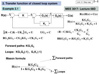
8. Transfer Function for Setpoint Changes
9. Transfer Function for Disturbance Changes
10. Simultaneous Changes Principle of superposition
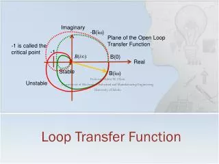
Open-loop transfer function
Obtained by multiplying all transfer functions in feedback loop
11. General Method Closed-loop transfer function
Z = any variable in feedback system
Zi = any input variable in feedback system Z and Zi
Pf = product of all transfer functions between Z and Zi
Pe = product of all transfer functions in feedback loop
Setpoint change
Disturbance change
12. Closed-Loop Transfer Function Example
13. Simulink Example >> gp=tf([6.37],[5 1]);
>> kv=0.0103;
>> kip=0.12;
>> km=50;
>> gc=tf([2.5 5],[0.5 0]); >> gcl=gp/(1+gc*kv*gp*km)
Transfer function:
15.93 s^2 + 3.185 s
-----------------------------------
12.5 s^3 + 46.01 s^2 + 90.72 s + 16.4