Download
1 / 24
350 likes | 709 Views
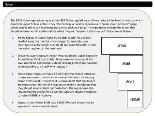
Electrical Noise. Wang C. Ng. Nature of electrical noise. Noise is caused by the small current and voltage fluctuations that are generated internally. Noise is basically due to the discrete nature of electrical charges. Externally generated noise is not considered here. Why study noise?.

E N D
Electrical Noise Wang C. Ng
Nature of electrical noise • Noise is caused by the small current and voltage fluctuations that are generated internally. • Noise is basically due to the discrete nature of electrical charges. • Externally generated noise is not considered here.
Why study noise? • It sets the lower limit for the detectable signals. • It sets the upper limit for system gains. • Develop mathematical models to take the effects of noise into account when analyzing electrical circuits/systems. • Find ways to reduce noise.
Thermal noise • Due to random motion of electrons. • It is ubiquitous (resistors, speakers, microphones, antennas, …) • It is directly proportional to absolute temperature. • White noise - Frequency independent up to 1013 Hz.
Thermal noise modeling • The noise amplitude is represented by the rms value:
Thermal noise modeling • The rms noise voltage for a 1-KW resistor is about 4 nV/Hz1/2. • The amplitude distribution is Gaussian with m = 0 and s = vn. • A series voltage source (vn) can be added to a resistor to account for the thermal noise.
Thermal noise modeling • Examples: • A 1-KW resistor in a system with a bandwidth of 100 MHz generates about 40 mV of noise voltage. • A 1-MW resistor in this system generates about 40 mV of noise voltage. • 10 1-MW resistor in this system generates about 0.4 V of noise voltage.
Shot noise • Shot noise is due to the random arrivals of electron packets at the potential barrier of forward biased P/N junctions. • It is always associated the a dc current flow in diodes and BJTs. • It is frequency independent (white noise) well into the GHz region.
Shot noise modeling • The noise amplitude is represented by the rms value:
Shot noise modeling • The rms noise current for a diode current of 1 mA is about 20 pA/Hz1/2. • The amplitude distribution is Gaussian with m = ID and s = in. • A parallel current source (in) can be added to a diode to account for the shot noise.
Shot noise modeling • Examples: • For a diode current of 1 mA in a bandwidth of 1 MHz shot noise generates about 20 nA of noise current. • For a diode current of 10 mA in a bandwidth of 100 MHz shot noise generates about 2 mA of noise current. • 100 diodes would generate .2 mA of noise current.
Flicker noise • Flicker noise is due to contamination and crystal defects. • It is found in all active devices. • It is inversely proportional to frequency (also called 1/f noise) . • DC current in carbon resistors cause flicker noise. • Metal film resistors have no flicker noise.
Flicker noise modeling • The noise amplitude is represented by the rms value:
Flicker noise modeling • The constant K1 is device dependent and must be determined experimentally. • The amplitude distribution is non-Gaussian. • It is often the dominating noise factor in the low-frequency region. • It can be described in more details with fractal theory.
Other noise types • Burst noise (popcorn noise):
System Noise Analysis Wang Ng
Introduction • Noise sources can be added to a device models to represent the effect of noise. • We need a means to characterize the noise performance of a system (black box). • Noise figure • Noise temperature
Noise figure • Used for resistive source impedance. • Most communication systems have a 50-W source impedance (Thevenin equivalent). • Signal-to-noise (S/N) ratio • Noise figure: F = (S/N)in / (S/N)out • F is a direct measure of the S/N ratio degradation caused by the system.
Noise figure calculations • For an ideal (noiseless) amplifier: Sout = G Sin Nout = G Nin • For a real system: F = (Sin/Nin)(Nout/Sout) = Nout/GNin or F = (Total noise)/(Noise due to input) • F in in general frequency dependent.
System noise • Internally generated noise can be computed from: Nsys = (F - 1)GNin since Nout = Nsys + GNin
Cascade systems • Gain: Gtotal = G1 G2 … GN • Noise figure: Ftotal = F1 + (F2 - 1)/G1 + (F3 - 1)/G1G2 + … + (FN - 1)/G1G2 … GN • What does this tell us? We should pay most attention to the reduce the noise of the first system (Why???)
Noise temperature • It is the temperature at which the noise generated from the source resistance equals to the system noise. • The noise temperature of a system is a better measure when F is close to 1 (low-noise system) • Noise temperature: Tn = T(F-1)
Radiometer • A modern radiometer can measure noise temperature variation down to 100th or even less in K. • This instrument can be used for remote sensing/imaging. • Possible extra credit presentation.
Summary • System noise measure: Noise figure and noise temperature • Internal noise calculation • Cascade system noise • First stage noise