Download
1 / 38
380 likes | 519 Views
Beam Monitoring and Control with FPGA Based Electronics. Nathan Eddy Instrumentation Department. Outline. FPGA Overview Example Applications at Fermilab Next Generation Wireless Observations on FPGA Systems Summary. Field Programmable Gate Arrays or… System on a Programmable Chip.

E N D
Beam Monitoring and Control with FPGA Based Electronics Nathan Eddy Instrumentation Department
Outline • FPGA Overview • Example Applications at Fermilab • Next Generation Wireless • Observations on FPGA Systems • Summary Nathan Eddy
Field Programmable Gate Arrays or…System on a Programmable Chip • Provide reconfigurable hardware implementations in a single chip solution • Combine the speed of hardware with flexibility usually associated with software • Features vary from basic logic and I/O to complete systems with dedicated RAM, DSP blocks, Clock Management, and advanced digital I/O capability • Used in a wide variety of applications • Cell Phones, Wireless, Radar, Image Processing, etc Doubles Every 18 Months Nathan Eddy
Up to 180k Logic Elements Up to 10MBits of RAM Able to implement true dual port ram & FIFOs Dedicated DSP blocks running at up to 500MHz Able to implement multiplies, multiply-accumulate, and FIR Filters Sophisticated Clock Management Circuitry Internal Phase Lock Loops for multiply, divide, and phase shifting clocks Dedicated Clock networks throughout the chip Single-end and Differential I/O for all common standards Up to 1100 user defined pins Very Flexible & Configurable The Bells and Whistles or…What’s in there? Nathan Eddy
Embedded Systems Hard Core Resource Allocation • Hard Core Embedded processor is a dedicated physical component of the chip, separate from the programmable logic • 2-4 times faster than Soft Core • Soft Core Embedded processor is built out of the programmable logic on the chip • A 32 bit RISC processor uses about few percent of total resources • Implementation of existing code directly in the FPGA without having to develop HDL code Soft Core Resource Allocation Nathan Eddy
Altera FPGA Families • Stratix I, II, & III • High end FPGA with all the features • Latest interfaces and fastest speed grades • Dedicated Adaptive Logic and DSP blocks • More logic, ram, variety of PLLs • Packages from 484 to 1760 pin FBGA • $200-$8000 depending on size & speed • Cyclone I & II • Low cost FPGA with scaled down features • Much the same feature set – No Adaptive Logic or DSP blocks • Less logic, less ram, less PLLs, slower • Packages from 144 (TQFP) to 672 (FBGA) pin • $10-$250 depending on size & speed Nathan Eddy
Benefits of FPGAs and Digital Design • Extreme flexibility inherent in FPGA • Algorithms and functionality can be changed and updated as needed • Code base which can be used for multiple projects • Intellectual Property (IP) cores provide off the shelf solutions for many interfaces and DSP applications • The speed of parallel processing • Can perform up to 512 multiplies simultaneously • The Pipeline nature of FPGA logic is able to satisfy rigorous and well defined timing requirements • Digital Design provides a straightforward simulation path for design development and verification • A variety of commercial tools available – MatLab, SimuLink, AccelDSP, etc Nathan Eddy
FPGA Based Instrumentation at Fermilab • Foster Digital Damper Board • Main Injector Dampers • Recycler Damper • VME Digital Damper Board • Recycler Adaptive RF Correction • Recycler ACBEAM Intensity Monitor • Replace Foster Boards in MI and Recycler • PBar Downconverter Digitizers • Developed as BPM electronics for AP3 • Used to “fix” MI SBD Timing problems Nathan Eddy
The Original Foster Board • Developed by B. Foster and A. Seminov • Required a number of blue wires and patches to get working • 4 of 5 boards made operational • Operated as the MI Damper system since 2004 • Numerous talks by B. Foster & P. Adamson • Used to implement the Recycler Transverse Damper System in 2005 Nathan Eddy
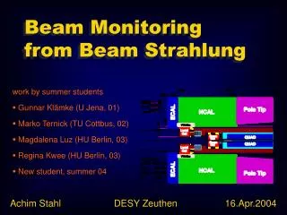
Recycler Transverse Instability Damper • Provide negative feedback to damp out transverse instabilities • Independent Horizontal and Vertical systems Nathan Eddy
Digital Filter Implemented in FPGA • Implemented a digital filter in the FPGA • Four sample boxcar average on the input remove 53MHz harmonics • One turn notch filter to remove revolution harmonics • Able to re-use ADC, DAC, and Clock interfaces from MI Damper • Uses Pipeline ability of the FPGA to control delays • All gains and delays are user controlled by registers implemented in the FPGA and tied to ACNET devices Nathan Eddy
Recycler Damper Commissioning and Performance • Able to implement the FPGA firmware for the system in a couple weeks • Commissioning took another 4-6 weeks • Pseudo Density • With no damper, observed instability induced beam loss when D > 0.8 • With the damper, routinely able to run with D as high as 1.5 with no beam loss • After commissioning, had one occurrence where the damper caused beam loss when the input RF clock went away during a Low Level RF system reset • Implemented RF clock verification algorithm in the FPGA which disables the damper and reports and error back to the control system Nathan Eddy
VME Digital Damper Hardware Digital Outputs • Next Generation Board • M. Larwill & N. Moibenko of PPD did schematics & layout • 3 Prototype boards • 15 Production boards • Can synchronize ADCs & DACs with external clock • All clocks controlled by Phase Lock Loops in FPGA • Traded Sharc for VME • Take advantage of existing controls software • Replace FIFOs with DDR RAM • Bigger FPGA and upgraded DACs • All interfaces in FPGA • Designed as Swiss Army Knife of Instrumentation DDR Sodimm 1 GByte 4 ch DAC 636MHz VME Huge FPGA RF Clock In 4 ch ADC 212MHz Max CPLD Extras Available– Ethernet USB LVDS serial Sharc LinkPort Digital Inputs Nathan Eddy
Recycler Low Level RF and Beam Distribution • Beam Profile can be predicted by looking at the Cavity Fanback • Martin Hu showed the profile could be improved by correcting the LLRF based upon the fanback • Need to correct distortions of Recycler Low Level RF barrier buckets • Amplifier response, cables, cavity response • Need a better than 1% correction on 2kV barriers Cavity Fanback Beam Distribution Nathan Eddy
Adaptive Correction for Recycler LLRF • Implement closed loop correction for LLRF drive signal based upon Cavity Fanback • Build a correction which is constantly adapting to system changes • The sampling is synchronous with the machine RF which allows the building of a one turn waveform of 588 53MHz samples • The averaging and the correction are done on the one turn waveform 588 Samples Per Turn 588 Samples Per Turn Nathan Eddy
Adaptive LLRF Correction Performance • The board has been integrated into the Recycler LLRF crate and operational since October • See about 10% variation on anti-proton bunch intensity delivered to TeV • The variation was more than 50% without the correction • Studies are still underway to optimize the system and further flatten the cold beam profile • Develop an analytical model for the system • Remove effect on transformers on inputs Correction Off Correction On Nathan Eddy
Recycler Intenstiy Monitor • The Recycler DCCT used to monitor the beam intensity is no longer working reliably and needs to be replaced • Likely to occur during next long shutdown • Need a reliable alternative to measure the beam intensity ASAP • Determine the intensity of the bunched beam by integrating the signal from a toroid • Problem is determining the baseline • Depends upon the intensity and distribution • Needs to work during injection/extraction and RF manipulations • A “smart” digitizer can help Nathan Eddy
ACBEAM Custom Digitizer Design Toroid Data 212MHz • Construct 588 sample 1 turn waveform • Use RRBeamSync to sync with turn marker • Keep a running sum of the last N turns • Currently N = 2 to 100, plan to increase it to 1000 • Able to re-use design from RF correction • The N Turn waveform and resulting integration can be latched upon request and then readout at leisure Σ Sum to 53Mhz N Turn Running Sum 588 Sample Waveform RAM RF Clock 53MHz VME 1 Turn Integral RRBeamSync Nathan Eddy
ACBEAM is Now Operational Time Drift RMS < 0.1e10 • Able to put together the hardware (FPGA) in a couple of days • System was designed, tested and commissioned in a few weeks (J. Crisp, A. Ibrahim, D. Voy) • Dependence on bucket length understood • Still studying the slow time drift (1% over a few hours) • Suspect dependency on the momentum spread of the beam Nathan Eddy
High Order Mode BPM from Tesla RF Cavity • Look at a dipole mode which couples strongly to the beam • Cavity imperfections cause polarization frequency split • Can determine the 4D (X, X’, Y, Y’) beam position from the amplitude and phase of the signals Single Bunch Coupler 1 Coupler 2 Nathan Eddy
HOM BPM Calculations Raw Data Mode Vectors Amplitudes k ~ 6, j ~ 100 to 4k Calibration Matrix 4D Position Nathan Eddy
Custom FPGA Digitizer Implementation FPGA • Need to read out raw data for mod*cav*coupler channels at 4k to 10k data points per for multibunch then perform dot products to determine mode amplitudes • The current system is unable to report a position for every pulse at 5Hz for single bunch even with only a few cavities per module enabled • Alleviate the I/O bottleneck and greatly reduce the processor load by calculating the mode amplitudes in the hardware • Store mode vectors in FPGA RAM and perform the dot product on the data as it comes in • This can be done in the digitizer hardware very efficiently by an FPGA • This can improve the processing time by several orders of magnitude for online measurements • Proto-type design being tested at DESY using VME Digital Damper S Coupler Data xn*vn,j Amplitudes Nathan Eddy
PBar Downconverter Digitizer • Developed by S. Hansen, B. Ashmanskas, D. Peterson, T. Kiper Nathan Eddy
Downconverter Digitizer as BPM • Designed as used as a BPM in the transfer line downstream of the Anti-proton production target • The original system was unable to see the anti-proton signals due to small amplitude signals and out of band kicker noise • Use analog downconversion to select 53MHz component of the signal • New system allows position measurements on anti-proton beam in AP3 line with ~100mm of resolution Kicker Noise Beam Signal Beam Envelope Nathan Eddy
PBar Downconverter as a Programmable Trigger Module • The Sampled Bunch Display (SBD) system is a scope based system used to record longitudinal bunch data for analysis • Was down for several weeks due to issues with old CAMAC timing system • Implemented a programmable delay trigger state machine to provide scope triggers • The triggers are synchronized with the turn marker from the RF system and completely user controlled • As an extra, we also implemented an MDAT decoder for readback of machine parameters like momentum on each trigger • The basic system was developed and commissioned in about a week MDAT Serial Link FPGA Trigger Module Turn Marker Ethernet Trigger Fast Scope Beam Signal Ethernet Nathan Eddy
NimBin FPGA Development Board • Developed from initial Downconverter Digitizer as cost effective general purpose FPGA instrumentation (S. Hansen, B. Ashmanskas, D. Peterson) • Similar to commercial development boards available but targeted for use in Fermilab • NimBin provides low overhead • Basic hardware for many applications • Monitoring and Feedback • Sophisticated Test Signal Source • Interface Testing • Currently 4 proto-type boards exist Nathan Eddy
Next Generation Wireless • Will use Multiple Input Multiple Output (MIMO) Technology • A key element is multipath which refers to reflections of RF waves in a physical environment • Spatially multiplexed orthogonal frequency multiplexing MIMO • Uses reflections to tune system performance and minimize errors • Increase transfer rate based upon multiple antennas • More data and better spectral density • Requires very sophisticated algorithms to run realtime • Scattering, diffraction, absorption are all considerations • Need a channel model to account for all of these effects • Software based mathematical models • Need a real world environment the MIMO system will operate in • Requires abiltiy to rapidly tune transmitter and receiver Nathan Eddy
MIMO System Transmitted Data • Use 2 to 4 antennas • Data Rate = BW * Ess * Num Attennas • BW is 20MHz/40MHz, Ess is spectral efficiency 2.7 to 3.6bps/Hz • Use Linear Algebra to decouple the channel matrix in spatial domain and recover the transmitted data • Matrix inversion, maximum likelihood detection (MLD), and SVD used to resolve signal • Has been demonstrated on FPGA based hardware at speeds up to 1Gbps • Flexibility of FPGA hardware allows fast testing and of new algorithms Received Signal Nathan Eddy
A Couple Observations on FPGA Electronics • FPGAs are digital objects and the effectiveness of any system is dependent upon it’s Analog interfaces • Timing is everything Nathan Eddy
The Analog Components – ADCs & DACs • Need to work with analog input signals • Beam pickups, Schottky detectors, Torroids, etc • Requires Analog to Digital Converters (ADCs) • Current ADC performance • Up to 2-3 GSPS with 8 bit precision • Up to 500 MSPS with 12 bit precision • Up to 100 MSPS with 14 bit precision • Need to produce analog output signals • To act on the beam – RF, kick signals, etc • Require Digital to Analog Converters (DACs) • Current DAC performance • Up to 1 GSPS with 14 bit precision • The effectiveness of FPGA solutions is largely dominated by the performance of the analog components and converters • Mixers can be used to downconvert or upconvert the signals • Speed needed is dictated by the bandwidth requirements Nathan Eddy
Parallel and Pipelined - Timing • Developing the algorithms and logic is often straightforward • With modern HDL languages very similar to writing C code • The details are in making sure timing requirements are met • Need to keep pipeline structure in mind when designing • Possible for a small change in a design to produce timing errors Nathan Eddy
Summary • FPGA are now the acknowledged leader of cutting edge fast DSP applications where speed and flexibility are needed • FPGA based electronics are being used to implement algorithms for beam control and monitoring systems • The flexibility of general purpose designs based upon FPGAs allows fast development & deployment of new systems • Provide convenient proto-types for future projects • The size, speed, and feature sets of FPGAs are growing by leaps and bounds while the cost is decreasing • How can we take advantage of the increased power of FPGAs for future accelerator control and monitoring? Nathan Eddy
Backup Slides Nathan Eddy
Adaptive Logic Block Nathan Eddy
From Design to Implementation FPGA Tool EDA Apps • FPGA tool is used to generate RTL for configuring FPGA • Provides simulation but can be tedious • Write HDL code and feed it to the FPGA tools • Can use IP like subroutines • MatLab/Simulink to FPGA tools with 3rd Party synthesis tool • C to FPGA tools with 3rd Party tools • Working towards plug and play orientated design • Easier to learn • Faster development Nathan Eddy
Recycler Transverse Damper Response Nathan Eddy
Recycler Damper Commissioning • Commissioning and checkout done by open loop VSA measurements of upper and lower tune lines • Make sure phase is correct at different rotation harmonics Nathan Eddy
Dipole Mode Response Nathan Eddy