Download
1 / 16
160 likes | 267 Views
BDS optics and minimal machine study. Deepa Angal-Kalinin ASTeC & The Cockcroft Institute Daresbury Laboratory. Contents. RDR BDS Design Minimal machine Proposed changes and implications to the BDS lattice design Layout possibilities Constraints Design criteria Upgrade path

E N D
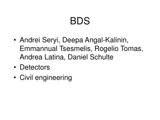
BDS optics and minimal machine study Deepa Angal-Kalinin ASTeC & The Cockcroft Institute Daresbury Laboratory LCWS08/ILC08
Contents • RDR BDS Design • Minimal machine • Proposed changes and implications to the BDS lattice design • Layout possibilities • Constraints • Design criteria • Upgrade path • Discussion LCWS08/ILC08
RDR BDS Design Linac Exit Beam Switch Yard Diagnostics Sacrificial collimators b-collimator E-collimator Final Focus Tune-up & emergency Extraction 14mr IR Tune-up dump Total length, BDS : 2226m Tune-up/fast extraction line : 467m Post collision extraction line: 300m Muon wall Main dump Extraction grid: 100m*1m LCWS08/ILC08
BDS RDR Design Criterion • Initial operation at (up to) 250 GeV; upgrade to 500 GeV by adding magnets only • no layout/geometry changes (beam dumps locations fixed) • Decimate dipoles : reduce ∫Bdl for 250 GeV operation by reducing lengths (i.e. number of dipoles); reserve space for additional dipoles to keep layout fixed • Quadrupoles & sextupoles unchanged • reduce ∫Gdl for 250 GeV operation by reducing strengths • Final Doublet magnets will have to be replaced for 500 GeV • Final Focus: 12 m “soft” bends divided into 5 × 2.4 m pieces • start with center piece only at each location • space reserved for remaining 4 pieces at each location for 500 GeV • Synchrotron Radiation Emittance Growth (DIMAD tracking; SYNC option 2) @ 250 GeV, emit/emit0 = 1.0036 @ 500 GeV, emit/emit0 = 1.0078 http://www.slac.stanford.edu/~mdw/ILC/2006e/doc/BDS2006e.ppt LCWS08/ILC08
Hybrid & Minimal (250 GeV) layouts Llinac→IP = 2226 m 19th September’06, ILC@SLAC BDS meeting Llinac→IP = 1530 m A.Seryi, Y. Nosochkov, M. Woodley LCWS08/ILC08
ILC2006s : Lattice details Llinac→IP = 1530 m Tune-up/Fast extraction: 318m A.Seryi, Y. Nosochkov, M. Woodley LCWS08/ILC08
ILC2006s : Optics ISR: Δεx/εx0 = 0.5 % A.Seryi, Y. Nosochkov, M. Woodley LCWS08/ILC08
Central Region Integration • Undulator-based positron source moved to end of linac (250 GeV point) • e+ and e- sources share same tunnel as BDS • upstream BDS (optimised integration) • Including 5GeV injector linacs • Removal of RDR “Keep Alive Source” • replace by few % ‘auxiliary’ source using main (photon) target • 500 MV warm linac, also in same tunnel • Damping Rings • in BDS plane but horizontally displaced to avoid IR Hall • Injection/Ejection in same straight section • Circumference • 6.4 km (current RDR baseline) • 3.2 km (possible low-P option) LCWS08/ILC08
Undulator location • Changes in BDS layout to accommodate this • Dogleg to provide clearance for the e+ photon target • TESLA design : switchyard to allow photons to the target as well as beam to second IR. LCWS08/ILC08
Dogleg : TESLA • 100 m for undulator + 300 m photon beam line (proposed 400m for ILC to reduce the offset of dogleg) • TESLA Transverse clearance at target (60cm) • Need more for ILC ? (remote control, 1m transverse concrete shielding). • ~100cm (need exact number). • Beam pipe can pass through this shielding but without any component LCWS08/ILC08
TESLA : emittance growth Horizontal emittance growth for the entire BDS, and a beam energy of 400 GeV (design emittance gex = 8 x 10⁻⁶ m). 14% emittance growth was considered to be acceptable. LCWS08/ILC08
Positron Source & BDS integration Existing 1TeV geometry BDS Some optimisation is available Longer photon drift to target would facilitate smaller transverse offset of primary e- dogleg TENTATIVE EXAMPE (WIP) N. Walker, Positron Source Workshop 29/10/08 LCWS08/ILC08
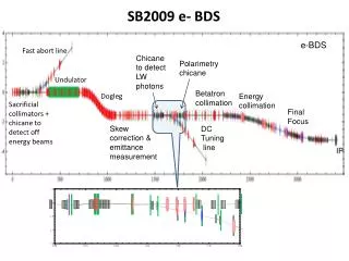
Layout possibilities • Fast extraction/tuning before undulator? This will protect the small aperture of the undulator. • Beam diagnostics (coupling correction and emittance measurement section) before the undulator? • before dogleg – no bends and tune-up dump • laser wire photon detection? • Polarisation measurement – probably better after the undulator? • Will need dedicated chicane for fast extraction : will add to the overall length. LCWS08/ILC08
Design Criterion • Dogleg : design criterion • How much emittance dilution is acceptable? • ISR emittance growth for ILC2006s (no dogleg) is 0.5% (criterion?) • Can dogleg be combined with energy collimation? • Order of collimation will be energy, betatron => collimation performance • Location of muon wall (possible DR injection) • Can we change the spoiler survival criterion to 1 bunch at 250 GeV? • Locations of energy and polarisation measurements LCWS08/ILC08
Upgrade path • Beam dump locations cannot be changed • Consider if having only one beam dump for tuning + post collision will save cost. • To extend the BDS backwards will not be possible due to undulator location? • To discuss… LCWS08/ILC08