Download
1 / 26
260 likes | 360 Views
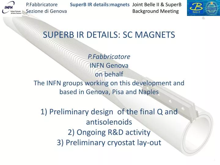
SUPERB IR DETAILS: SC MAGNETS P.Fabbricatore INFN Genova on behalf The INFN groups working on this development and based in Genova , Pisa and Naples 1) Preliminary design of the final Q and antisolenoids 2) Ongoing R&D activity 3) Preliminary cryostat lay-out .

E N D
SUPERB IR DETAILS: SC MAGNETS P.Fabbricatore INFN Genova on behalf The INFN groups working on this development and based in Genova, Pisa and Naples 1) Preliminary design of the final Q and antisolenoids 2) Ongoing R&D activity 3) Preliminary cryostat lay-out
We are developing the magnets of the IR on the basis of the IR design made by M.Sullivan
The quadrupoles are done according the double helix principle. This lay-out allows to modulate the winding introducing suitable multipole corrections. The overall structure is compact and the effect of coil ends on field quality is minimal (wrt more conventional designs)
The superconducting wire Preliminarly the sc wire chosen for these coils if a NbTi multifilamentary wire already involved in CMS conductor. The diameter is 1.28 mm; the Cu/SC ratio is 1.1
Quench issues Simple quench simulations indicate potential problems (The problem!) This is due to the high current density in the wire: 2kA/mm2 (5 times the one in LHC dipoles)
Quench propagation in 2 directions help, but the basic problem remain of excessive local heating
Mitigation In facts quench scenario is better because: As current decay, the eddy current induced in the mandrel will heat up the coil (quench back) better distributing the temperature increase; induced currents also dissipates energy in the mandrel reducing the amount of energy dissipated in the winding. ac losses in the sc wire help in quenching larger regions. A test of the model is crucial for understanding these issues.
Construction of a model coil for addressing quench issues The coil has been constructed at ASG Superconductors and was successfully tested at 4.2 K at INFN.
The model With 60 turns this coil generates a gradient of 50 T/m at 2600 A The stored energy is 1.1 kJ (2 times QD0). The current density is the same of QD0
For limiting quench problems … …weused a transformer system for charging the model so to limit the energy which in case of in case of quench can be dissipated as heat (1150 J) As primary we use a large magnet we have in lab Lp=6H ; Lc= 330 mH The ideal current transformer ratio is for Ls=Lc, but the energy would double. Using a reduced secondary inductance Ls=90 mH the current transformer ratio is still acceptable. In order to fast dump the current and extract energy from the coil, a heater is placed in the secondary winding.
The secondary was built and tested. It is done by a bi-filar wire of the same type involved for the quadrupole. In a single wire current up to 3000 A was induced. After quench the sc conditions were soon restored in the wire. Very good and promising result!
The model was successfully tested; it was fed with a current of 2750 A. The limitation seems to be of mechanical nature (mechanical disturbances). Further test are planned for better investigate this aspect.
Moving towards an updated design • The tests gave indications that high current could be involved (2750 A) • We are developing a design with angles of 35o and high current. With respect the model we also reduced the thickness of each layer down to 2.5 mm (4 mm used for the model). The pitch is the minimum one (turns touch each other) • The wire is the CMS one with formvar (Φ 1.28 + 0.08= 1.36 mm) or a Nb3Sn wire Φ 1.20 + 0.14= 1.34 mm R ext II layer R aver II layer R int II layer R ext I layer R aver I layer R int I layer R aperture
Main characteristics of allmagnets last version (notyetfrozen)
Margins (QD0H) with NbTi technology At T=4.2K the margin on the current is 70% DT =1.2K) At T=1.9 K the margin on current is 42% DT =3.7 K
Margins (QD0H) with Nb3Sn technology Involving Nb3Sn (much more difficult technology) we could operate with a larger margin, but limitations can arise due to thermo-magnetic instabilities at low fields. Fermilab studies It would be better operating at higher temperature (Supercritical helium) or using a wire 1.2 mm diameter but lower Ic
The coil axial dimensions just allows to accommodate them into the cryostat, provided that: 1) The cold bore of the coils coincides with the inner cold bore of the cryostats and it is made of Al alloy 2) The position of the coil is acceptable The present cryostat has 370 mm OD. The suspension system not yet studied. It shall be design to hold high axial forces (4 t)
Backward Forward
Next Steps of model development and coil design Construction of a NbTi prototype of QD0 April 2012 Construction of a Nb3Sn prototype of QD0 July 2012 2.b) Construction of a NbTi prototype of QF1 July 2012 3) Cryogenic test of the prototypes Sept. 2012 4) Finalize coil magnetic design Oct. 2012 5) Cryostat preliminary design Oct. 2012 The superconducting wire