Download
1 / 38
560 likes | 1.03k Views
CHAPTER 5 – FORMATION EVALUATION. CONTENTS. Mud Logging Coring Open-hole Logging Logging While Drilling Formation Testing Cased Hole Logging. Formation Evaluation. What is Formation Evaluation?

E N D
CONTENTS Mud Logging Coring Open-hole Logging Logging While Drilling Formation Testing Cased Hole Logging
Formation Evaluation • What is Formation Evaluation? • Formation Evaluation (FE) is the process of interpreting a combination of measurements taken inside a wellbore to detect and quantify oil and gas reserves in the rock adjacent to the well. FE data can be gathered with wireline logging instruments or logging-while-drilling tools . • Study of the physical properties of rocks and the fluids contained within them. • Data are organized and interpreted by depth and represented on a graph called a log (a record of information about the formations through which a well has been drilled).
Formation Evaluation • Why Formation Evaluation? • To evaluate hydrocarbons reservoirs and predict oil recovery. • To provide the reservoir engineers with the formation’s geological and physical parameters necessary for the construction of a fluid-flow model of the reservoir. • Measurement of in situ formation fluid pressure and acquisition of formation fluid samples. • In petroleum exploration and development, formation evaluation is used to determine the ability of a borehole to produce petroleum.
Mud Logging • Mud logging (or Wellsite Geology) is a well logging process in which drilling mud and drill bit cuttings from the formation are evaluated during drilling and their properties recorded on a strip chart as a visual analytical tool and stratigraphic cross sectional representation of the well. • Provide continuous record of penetration rate, lithology and hydrocarbon shows. • These information supports wireline log data. • From the cuttings, an oil stains or odor of oil may be detected, become an excellent qualitative indicator. • The fluorescent lamp is also a great help in detecting oil shows.
Mud Logging • The gas record and lithological sample are plotted along with surface parameters such as rate of penetration (ROP), Weight On Bit (WOB),rotation per minute etc. on the mudlog which serve as a tool for the drilling engineers and mud engineers. • Some problem: a discrepancy between the time the rock was drilled and the time it reached the surface – particularly for deep wells, where it take two or move hours to reach the surface.
Coring • One way to get more detailed samples of a formation is by coring, where formation sample is drilled out by means of special bit. • This sample can provide: • Detailed lithologicaldecscription. • Porosity, permeability, fluid saturation and grain density. • These parameters are measured in the laboratory and serve as a basis for calibrating the response of the porosity logging tools and to establish a porosity/permeability relationship.
Coring • Two techniques commonly used at present. The first is the "whole core", a cylinder of rock, usually about 3" to 4" in diameter and up to 50 feet (15 m) to 60 feet (18 m) long. • It is cut with a "core barrel", a hollow pipe tipped with a ring-shaped diamond chip-studded bit that can cut a plug and bring it to the surface. • Taking a full core is an expensive operation that usually stops or slows drilling operation, and can be done only before the drilling has been done. Coring Tool & Core Barrel
Coring • The other, cheaper, technique for obtaining samples of the formation is "Sidewall Coring". In this method, a steel cylinder—a coring gun—has hollow-point steel bullets mounted along its sides and moored to the gun by short steel cables. • The coring gun is lowered to the bottom of the interval of interest and the bullets are fired individually and the core will be retrieved. • Advantages of this technique are low cost and the ability to sample the formation after it has been drilled.
Core Preservation • Once the core is retrieve to surface then it is important that it should remain as unchanged as possible. • The core should be prevented from drying out, coming into contact with oxygen or being mechanically damaged. • Core barrel is filled with resin to prevent the core from moving and to minimize the exposed surface area. • Freezing the core in freezer containers. • Core sample is wrapped in a plastic film, aluminium foil and then dipped in molten wax.
Core Analysis • Can be divided into two categories: • Conventional Core Analysis. • Special Core Analysis. • Conventional Core Analysis. • The core is usually slabbed, cut lengthwise to make the structure visible. • Provides information on lithology, residual fluid saturation, ambient porosity, ambient gas permeability and grain density.
Gas Permeameter Liquid Permeameter
Core Analysis • Special Core Analysis : • Provides the following information: • Porosity and permeability at elevated confining stress. • Electrical properties such as formation factor and resistivity index. • Capillary pressure. • Wettability and relative permeability. • Mechanical rock properties such as compressibility. • Waterflood sensitivity for injectivity and well performance.
Open-hole Logging • Open-hole logging, also known as well logging is the practice of making a detailed record (a well log) of the geologic formations penetrated by a borehole. • Open hole logs are run before the oil or gas well is lined with pipe or cased
Principal of Well Logging • A well log is a record of certain formation data versus depth. • The appropriate downhole logging tools instrument called ‘sonde’, about 3.5 inches in diameter is lowered into mud-filled hole on logging cable. • This tools will measure the electrical, acoustic, and radioactive properties of the formation. • The result will be analyzed to determine which of the layers are porous and permeable, and likely to contain hidrocarbon. • A depth calibration wheel records the length of cable in the hole.
Principal of Well Logging • Survey is normally done from the bottom up. As the sonde is pulled up the hole, a continuous measurement signal is sent to the surface where the data is processed and recorded as a curve.
Electrical Logs • Developed by Conrad & Marcel Schlumberger (who founded Schlumberger Limited), and intoduced to the US in 1929. • Can be divided into two main types: measurement of natural electrical current in the rock (SP Log), and measurement of induced electrical current (Resistivity Log and Induction Log).
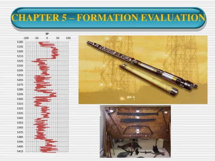
(1) Spontaneous Potential (SP) Log • Also known as Self Potential Log. • SP Log record weak electrical currents that flow naturally in the rock next to the wellbore (natural electricity). • The log shows the boundaries and thickness of each layer of rock, especially permeable (sandstone) and impermeable (shale). • Because the SP Log is so simple to obtain and provide such basic information, it is the most common log. Shale Sandstone Shale Sandstone Shale
(1) Spontaneous Potential (SP) Log • Useful for: • Detecting permeable beds and it thickness. • Locating their boundaries and permitting correlation of such beds. • Determining formation water resistivity. • Qualitative indication of bed shaliness. Shale Sandstone Shale Sandstone Shale
(2) Resistivity Logs • Use to measure the resistivity of the formation, and thus the possibility of hc shows. • A sonde sends an electrical signal through the formation and relays it back to a receiver at the surface (induced electricity). The surface detector will measure the formation’s resistance to the current. • A rock which contains an oil and/or gas saturation will have a higher resistivity than the same rock completely saturated with formation water.
(3) Induction Logs • Use to measure the conductivity of the formation, and thus the possibility of hc shows. • A rock which contains an oil and/or gas saturation will have a lower conductivity than the same rock completely saturated with formation water. • Induction logs use an electric coil in the sonde to generate an alternating current loop in the formation by induction. • Induction tools t give best results when mud resistivity is high with respect to formation resistivity, i.e., fresh mud or non-conductive fluid. In oil-base mud, which is non conductive, induction logging is the only option available.
(4) Dielectric Logs • Responds essentially to water and is unaffected by the presence of hydrocarbons. • Particularly important in determining the irreducible water saturation when oil-based muds are used.
Nuclear Logs • Just as SP and resistivity logs record natural and induced electrical currents, nuclear logs (also called radioactivity logs) record natural and induced radioactivity. • Three type of logs: Gamma Ray Log, Neutron Log and Formation Density Log.
(1) Gamma Ray Log • Record the natural γ-radioactivity of rocks surrounding the borehole. • The γ-radiation arises from three elements present in the rocks, isotopes of potassium, uranium and thorium. • Useful for defining shale beds because K, U and Th are largely concentrated in association with clay minerals. • It is used to define permeable beds when SP log cannot be employed (eg. When Rmf = Rw). Shale Sandstone Shale Sandstone Shale
(2) Neutron Log • To obtain a neutron log, a sonde sends atomic particles called neutrons through the formation. • When the neutrons collide with hydrogen, the hydrogen slows them down. • The response of the devise is primarily a function of the hydrogen nuclei concentration. • When the detector records slow neutrons, it means a lot of hydrogen is present – main component of water and hydrocarbon, but not of rocks. • Considered as porosity log because hydrogen is mostly present in pore fluids (water, hydrocarbons) the count rate can be converted into apparent porosity.
(3) Formation Density Log • This devise measure number of photon then be related to electron density of the formation. • Electron density is related to an apparent bulk density which equivalent to formation bulk density. • Useable to detect formation lithology.
Sonic or Acoustic Logs • Provide continuous record of the time taken in microsecond/foot by sound wave to travel from the transmitter to the receiver n the sonde. • Velocity of sound through a given formation is a function of its lithological and porosity. • Dense, low porosity rocks are characterized by high velocity of sound wave and vise-versa for porous and less dense formation.
Logging While Drilling • One of the major drawbacks of wireline information is that it is received several hours to several weeks after the borehole is drilled. • During this time period, the formation can undergo significant alteration, especially in its fluid saturation, effective porosity, and relative perm. • LWD allow wireline-type information to be available as near as real-time as possible. • Logging While Drilling (LWD) is a technique of conveying well logging tools into the well borehole downhole as part of the bottom hole assembly (BHA).
Logging While Drilling • Some available measurement in LWD technology: • Gamma Ray • Resistivity • Density • Neutron • Sonic (fairly recent) • Formation pressure • Formation fluid sampler • Borehole caliper (Ultra sonic azimuthal caliper, and density caliper).
Formation Testing • Is a means of obtaining information concerning the liquid and pressure in an open-hole formations. • Three methods: • Wireline testing • Drill stem test (DST) • Well Test Analysis
Wireline Testing • Provide reservoir fluid samples, reservoir pressure, an indication of fluid mobility and information on reservoir continuity. • Two types: Repeat Formation Tester (RFT) and Formation Interval Tester (FIT). • The RFT is run into the hole and a continuous digital readout of hydrostatic pressure is obtained. • At any point in the hole the tool may be actuated to force a rubber pad against the wall of the hole, and a tube in the centre of the pad is forced hard against the formation. • The formation fluid will flow to the chamber through the tube.
Wireline Testing • The FIT is used for single test – only one pressure reading and one fluid sample for each run. • A tool is actuated (a pad is tightly against the formation to form a seal against hydrostatic pressure of the fluid in the hole). • A shaped charge is then fired into the fm, opening a passageway for fm fluids to flow into a chamber in the tool. At he same time the fm pressure will be recorded.
Drillstem Test (DST) • A drill stem test (DST) is a procedure for isolating and testing the surrounding geological formation through the drill stem. • The test is a measurement of pressure behavior at the drill stem and is a valuable way to obtain important sampling information on the formation fluid and to establish the probability of commercial production. • The test is made by lowering a valve, a packer, and a length of perforated tailpipe to the level of formation. • The packer set against the wall of the borehole so that it seals off the test interval from the mud column above.
Drillstem Test (DST) • The valve is then opened, and the fm fluid will flow to the surface through the drillpipe. • The amount of fluid produced will represent the fluid production can be expected from the well.
Well Test Analysis • Two types of testing: pressure build-up and draw down test. • The primary objectives of well testing are to establish: • Permeability thickness (Kh) and permeability (K) • Stratification (by sequential testing of layer). • Well productivity. • Investigate reservoir boundaries and size. • The amount of fluid produced will represent the fluid production can be expected from the well.
Cased-hole Logging • Two major areas of cased-hole logging: • Production logging. • Reservoir monitoring. • Production logging refers to obtaining production or injection profiles over a completed interval. • Reservoir monitoring refers to obtaining real time information about changes in hydrocarbon saturation. • Crucial for understanding water contact movement. • Other services include cement bond log which used to evaluate the degree of isolation provided by the casing cement.